[Guide] Wire your LCD Display to the Pi Zero
Posted: Wed Jul 13, 2016 1:35 am
Hello there fellow Sudo-Modians,
since i've seen a lot of people doing their wiring wrong,
i wanted to write a little guide on how to wire your LCD Display Board to the Raspberry Pi Zero for testing purposes.
With this following guide you can test
- if your display runs on 5v
- if your display works
- the quality of the display
It is for testing only, as you will change the wiring later, when you've implemented the Power Supply (PowerBoost or alternative).
Here is a little Picture Guide on what to solder where:
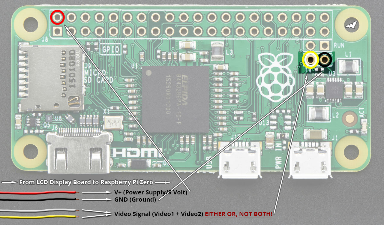
As you can see, your Display Board should have 4 wires. You will need to solder on 3 of them.
Those 4 wires are the following:
Red: V+ or 5v input. This is where your LCD gets its power from.
Black: GND or Ground. This is the ground or - if you will, of your LCD.
White: One of 2 Video Inputs. This is where it gets it's video signal from.
Yellow: The second Video Input. Most LCD Boards got 2 Inputs to change between 2 sources.
As wrote before, you will only need 1 of those Video Inputs to be wired onto the Pi0! NOT Both!
You have to find out which video input your display is using. Either use the usually included buttons to change the input,
or just solder on the other wire (Yellow/White) and test it with this one.
Your RPi0 should look as following, after soldering on the wires: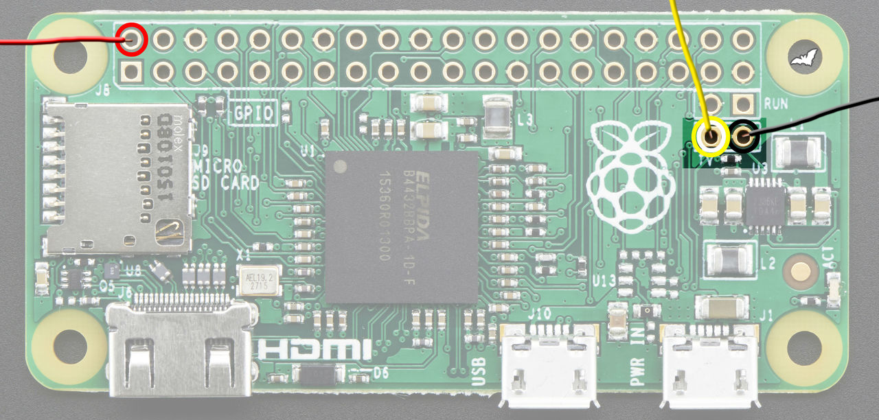 OR
OR
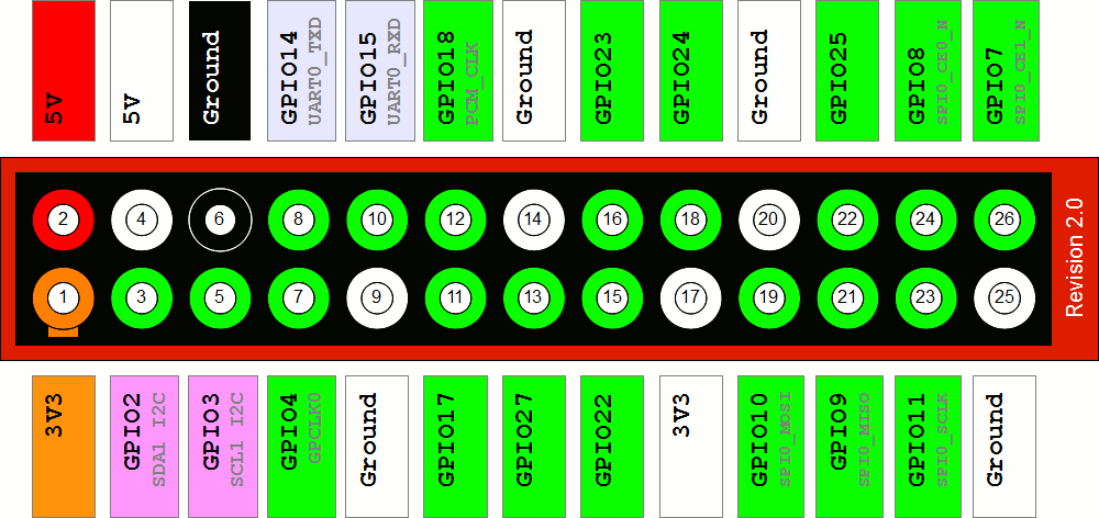
 I know a lot of you also solder the Red and Black wires onto the Pis USB Power Supply pads.
You should refrain from this. Sure, if works and it usually will not cause any problems in most setups.
But those are the pads for SUPPLYING the Pi with its needed power, not the pads that the PI has to supply modules and stuff.
Those are located in the GPIO Area and those are there for a reason.
You COULD starve the Pi from its needed power if your display needs too much power,
especially during the startup phase. This can cause your Pi to turn off during boot and corrupt your SD Card.
Again, this is unlikely but why take a risk if you can avoid this by simply using the Pins that are meant for this stuff?
-
Well, that's it. This is how you wire up your LCD Board to the Pi Zero for testing the Display.
As wrote before, this wiring will change, as you will solder the Red and Black wire to your Power supply later, in the final build.
Good luck!
since i've seen a lot of people doing their wiring wrong,
i wanted to write a little guide on how to wire your LCD Display Board to the Raspberry Pi Zero for testing purposes.
With this following guide you can test
- if your display runs on 5v
- if your display works
- the quality of the display
It is for testing only, as you will change the wiring later, when you've implemented the Power Supply (PowerBoost or alternative).
Here is a little Picture Guide on what to solder where:
As you can see, your Display Board should have 4 wires. You will need to solder on 3 of them.
Those 4 wires are the following:
Red: V+ or 5v input. This is where your LCD gets its power from.
Black: GND or Ground. This is the ground or - if you will, of your LCD.
White: One of 2 Video Inputs. This is where it gets it's video signal from.
Yellow: The second Video Input. Most LCD Boards got 2 Inputs to change between 2 sources.
As wrote before, you will only need 1 of those Video Inputs to be wired onto the Pi0! NOT Both!
You have to find out which video input your display is using. Either use the usually included buttons to change the input,
or just solder on the other wire (Yellow/White) and test it with this one.
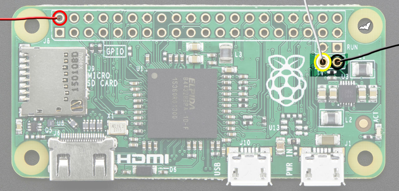
Your RPi0 should look as following, after soldering on the wires:
Yellow Wire soldered onShow
White Wire soldered onShow
You should refrain from this. Sure, if works and it usually will not cause any problems in most setups.
But those are the pads for SUPPLYING the Pi with its needed power, not the pads that the PI has to supply modules and stuff.
Those are located in the GPIO Area and those are there for a reason.
You COULD starve the Pi from its needed power if your display needs too much power,
especially during the startup phase. This can cause your Pi to turn off during boot and corrupt your SD Card.
Again, this is unlikely but why take a risk if you can avoid this by simply using the Pins that are meant for this stuff?
-
Well, that's it. This is how you wire up your LCD Board to the Pi Zero for testing the Display.
As wrote before, this wiring will change, as you will solder the Red and Black wire to your Power supply later, in the final build.
Good luck!
 [/spoiler]