Hello again! It took a littler longer than I’d hoped to get an Adafruit screen (I almost gave up and used a backup camera screen), but I finally got one a few days ago, so here’s part 3!
This time we’ll be mounting the screen in the case, modifying its controller board to run off 5v, making a breakout board to let us control brightness/contrast from the battery compartment, and creating that bracket I mentioned using the screw posts that you (hopefully) saved from the first part.
If you get stuck or need help with anything, stop by the forums!
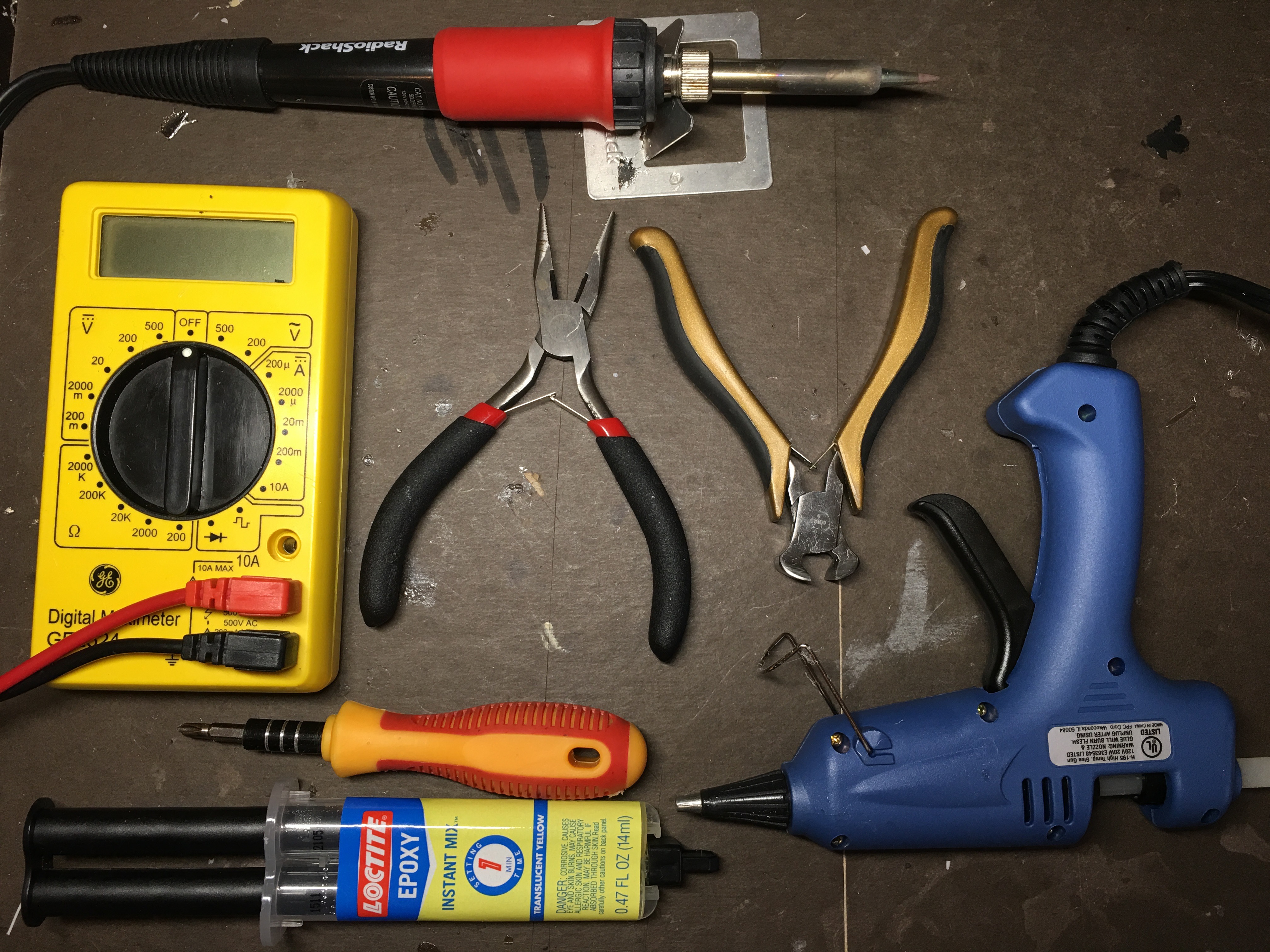
These are the tools I used this time. Nothing too crazy.
And these are the parts we’ll be using:
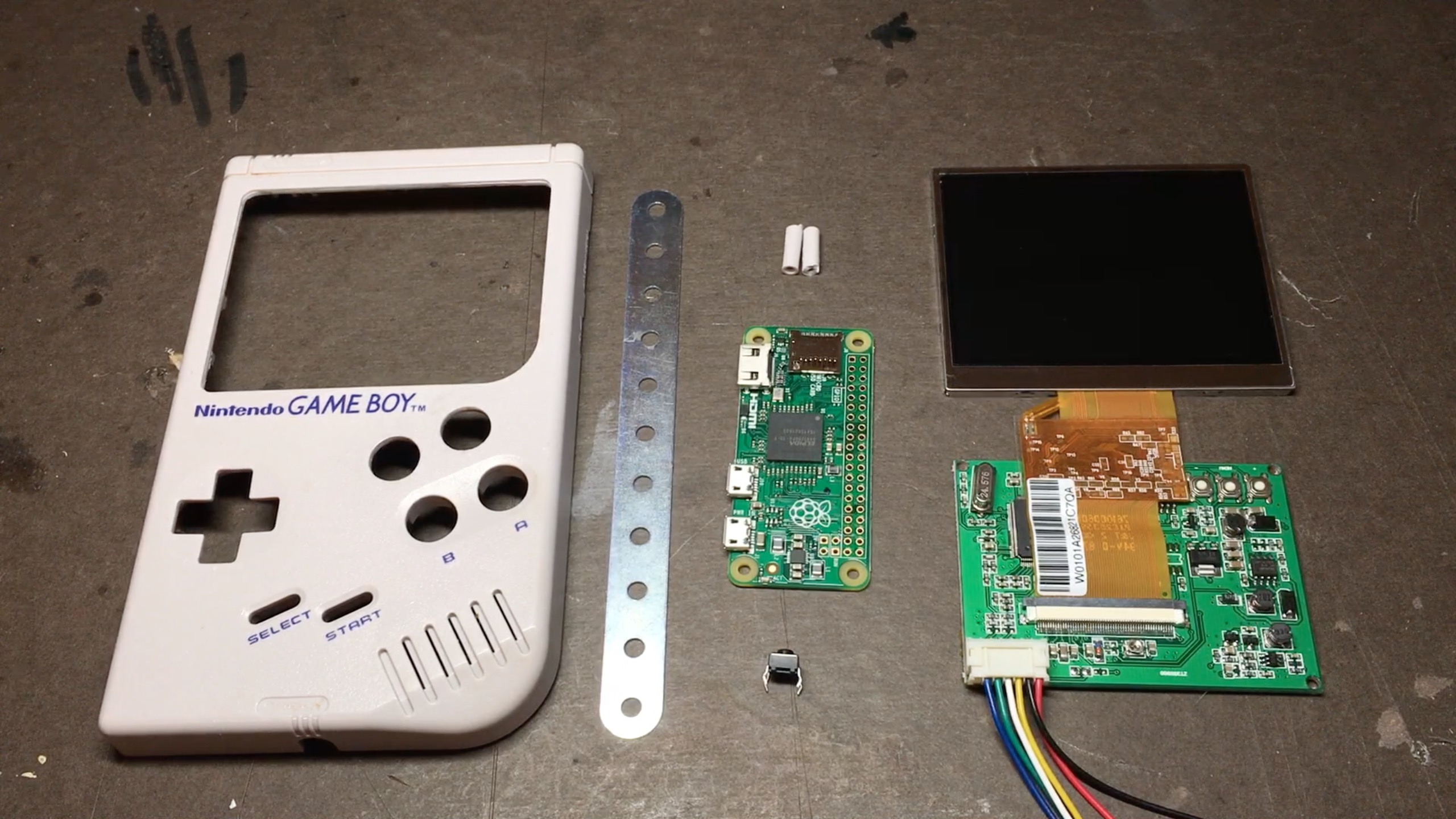
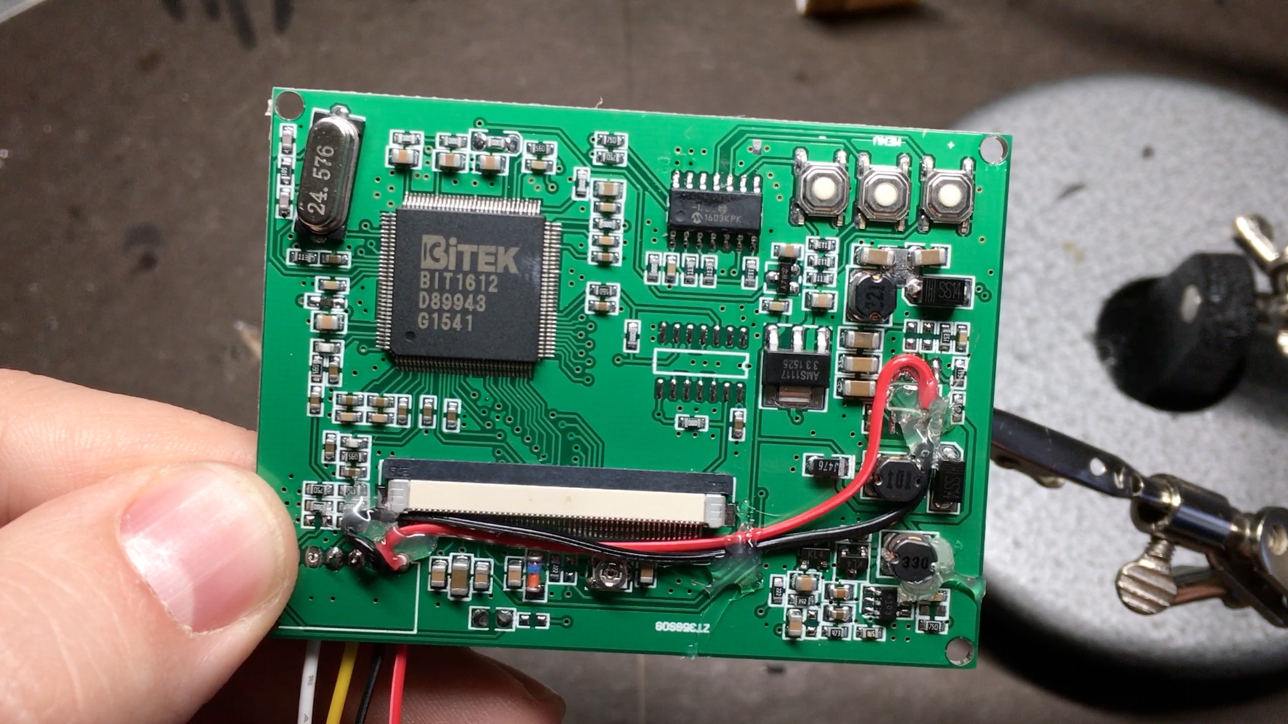
I’m doing this guide with the Adafruit 3.5″ composite display. There are other options out there as I’ve posted about in the past, but this is what I used in the original GBZ, and when you can find it in stock, you know exactly what you’re getting (which is not always the case when buying a backup camera screen off of Amazon to gut and use).
I should point out that you’ll obviously be blowing any kind of warranty or return-policy on this screen to smithereens with what we are about to do, so it’s a good idea to test it out and make sure it even works in the first place. I’ll show you how to test it on the Pi Zero itself further down in the guide if you’d like to do that.
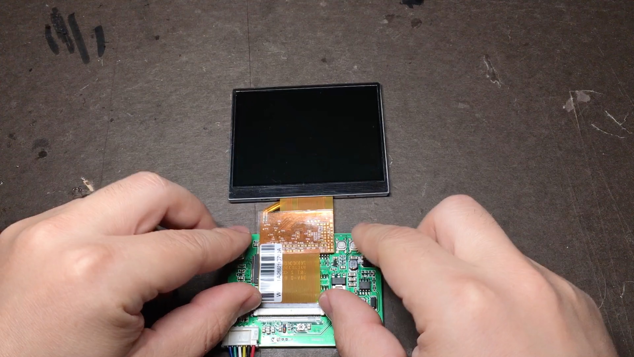
Start by carefully disconnecting the screen from the controller board by pushing the black tabs toward the screen with your fingernails. The ribbon cable is very fragile and not easy (if it’s even possible) to repair.
To modify the screen’s controller board to make it run off 5v, we have to remove a regulator from it, and connect two of the pads where it sat, to the power pins on the board. There is another guide for doing this with this same screen over on Adafruit that you can check out as well.
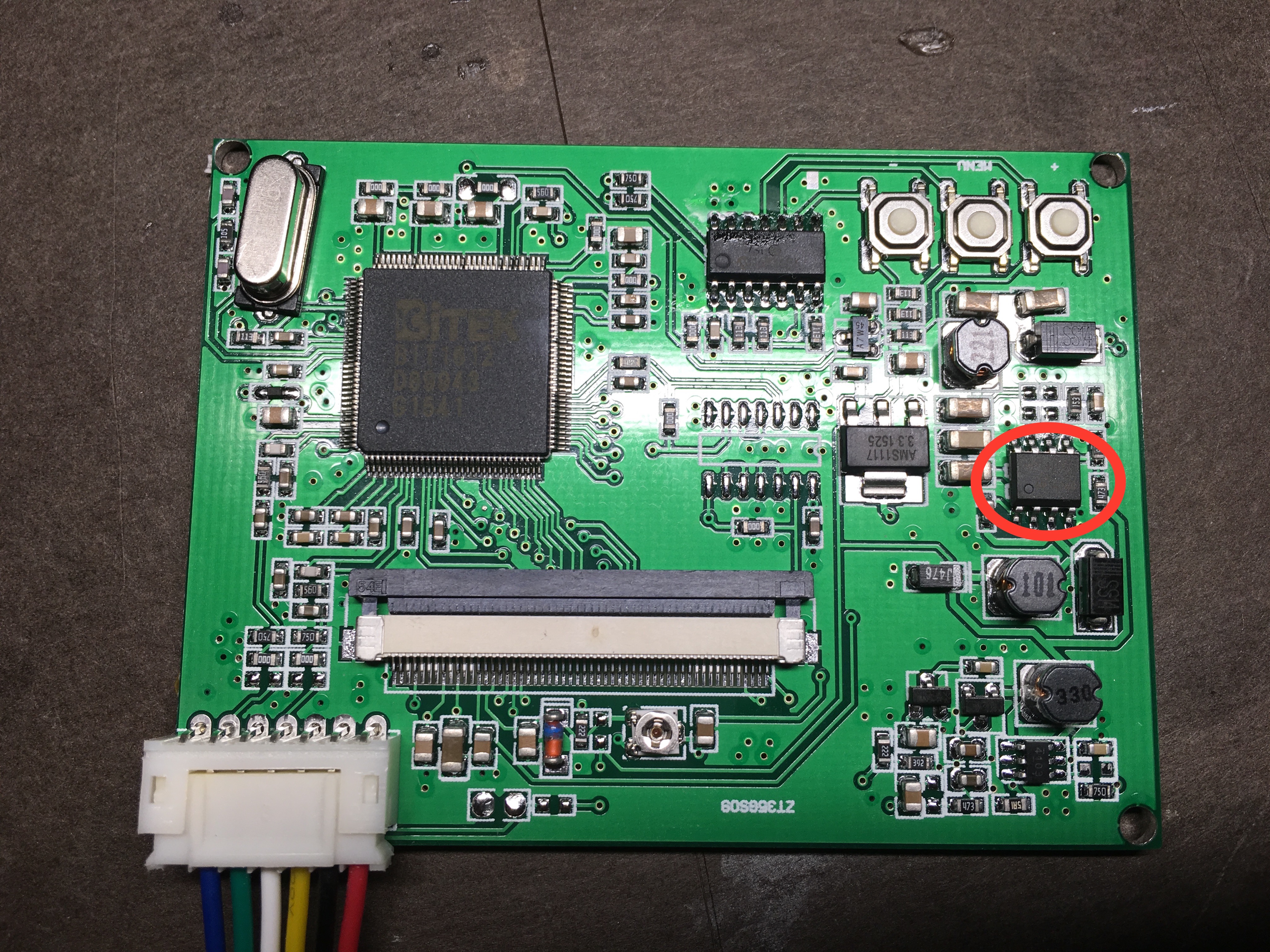
To remove the regulator, stick a big blob of solder across all the pins on either side. Gently pull one side up while you heat the whole blob of solder on that side. Keep alternating sides until it comes loose (check out the video for a demonstration):

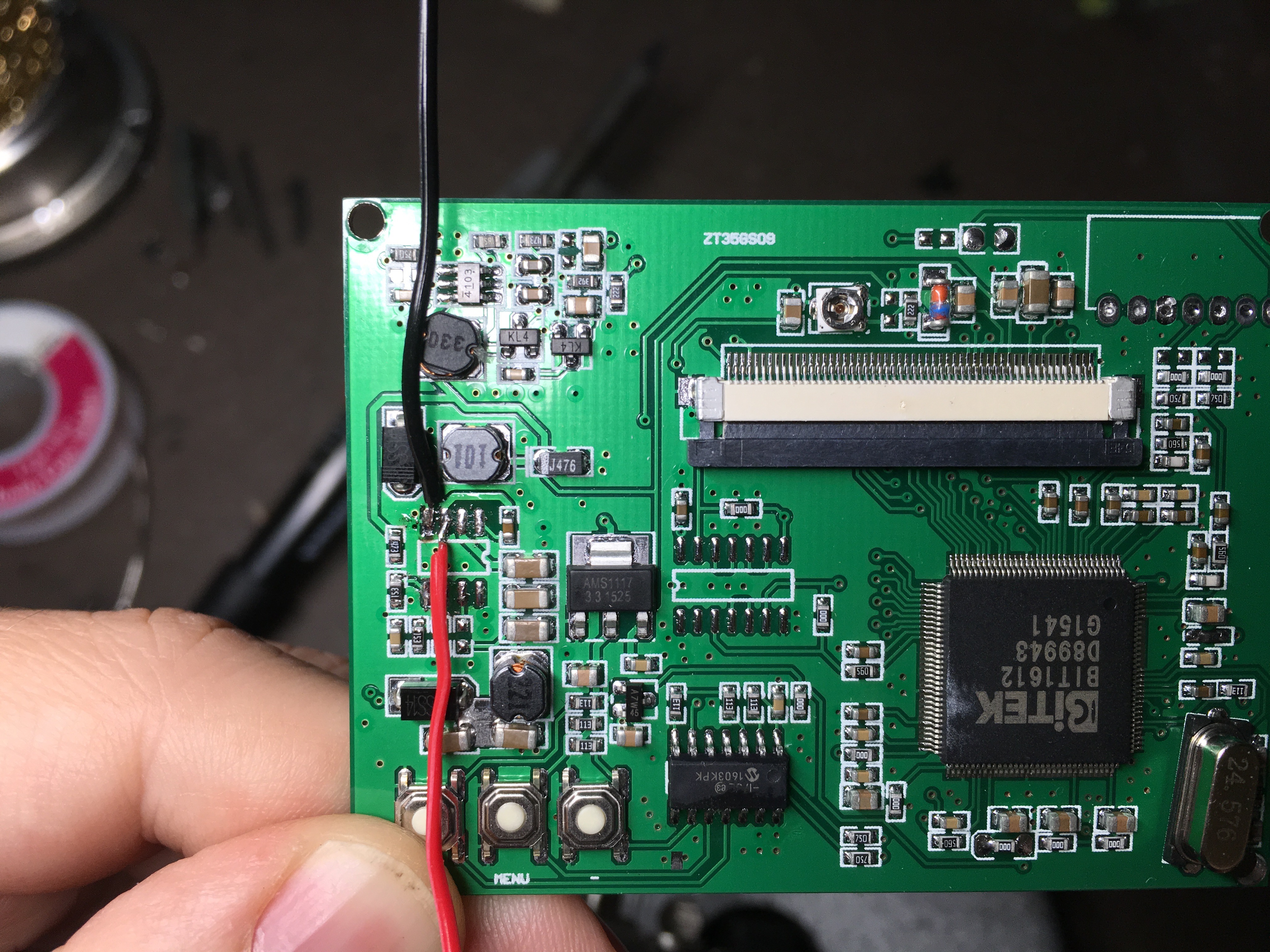
The two pins you want to connect to are the bottom-right ones (from this perspective, anyway):

Red is of course 5v, black is ground.
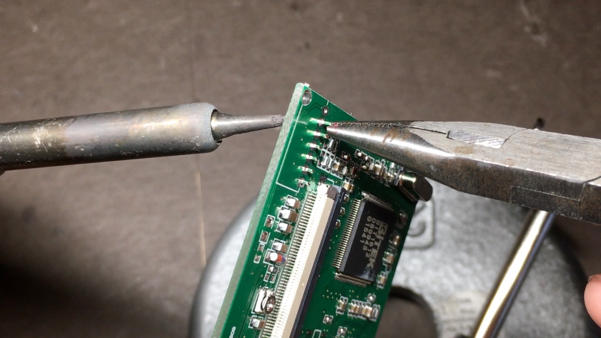
Next, remove the connector on the other side. You *might* be able to get away without doing this, but it removes a good chunk of bulk from the board which is nice. I found it easiest to snip the pins from the side:

And then remove the pins one by one by heating one side while gently pulling at the other side:
Now wire up the red/black wires you just attached to the corresponding pinholes you just freed up:
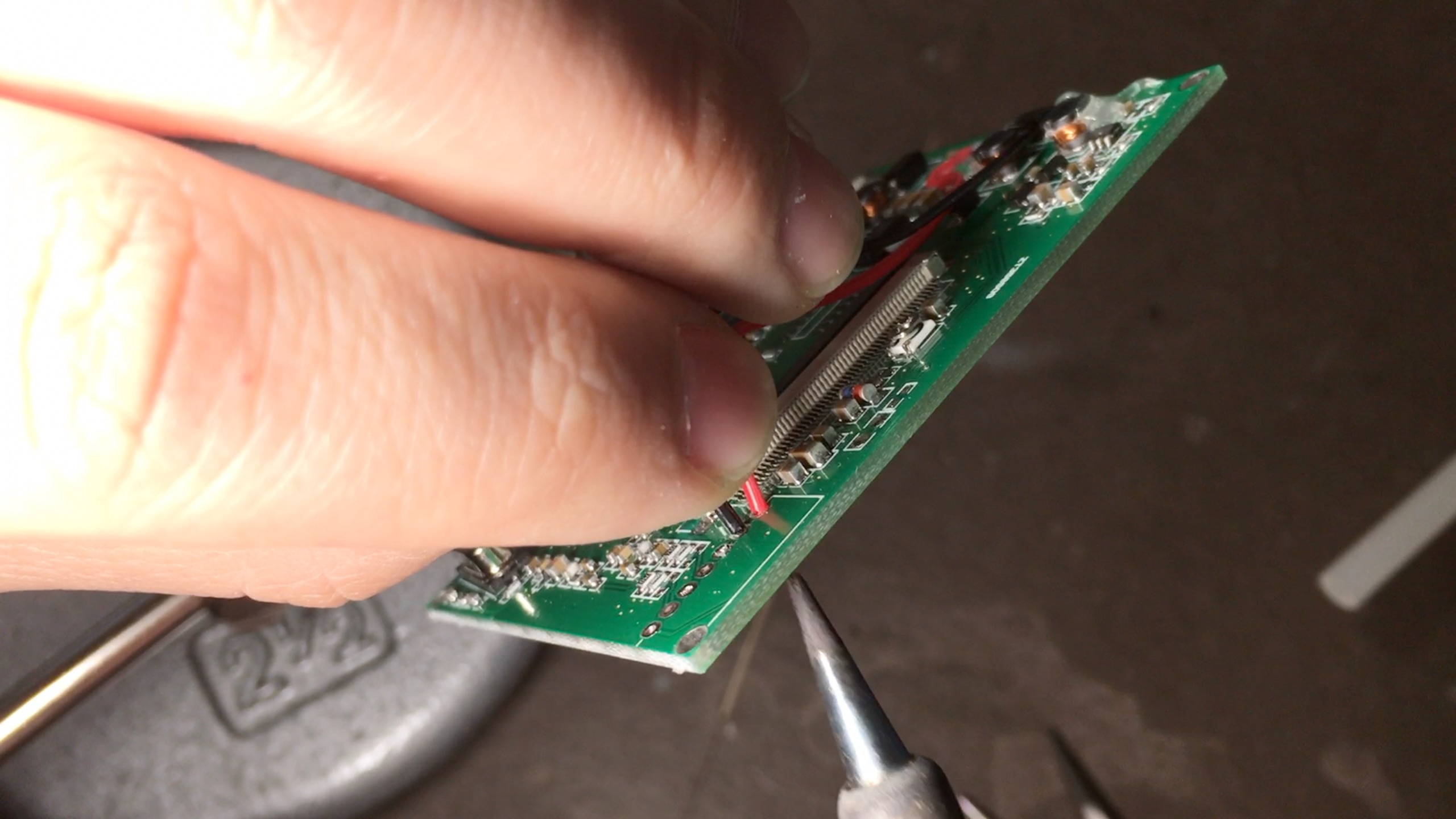
Then on the other side, attach red, black, yellow and white wires for you to actually use to attach it to the pi:
I’m paranoid about solder joints breaking while I work on things, so I usually hot-glue stuff like this down (it’s relatively easy to peel off if you want/need to).
Here’s what it should look like when you’re done:
Now you should test it to make sure it still works.
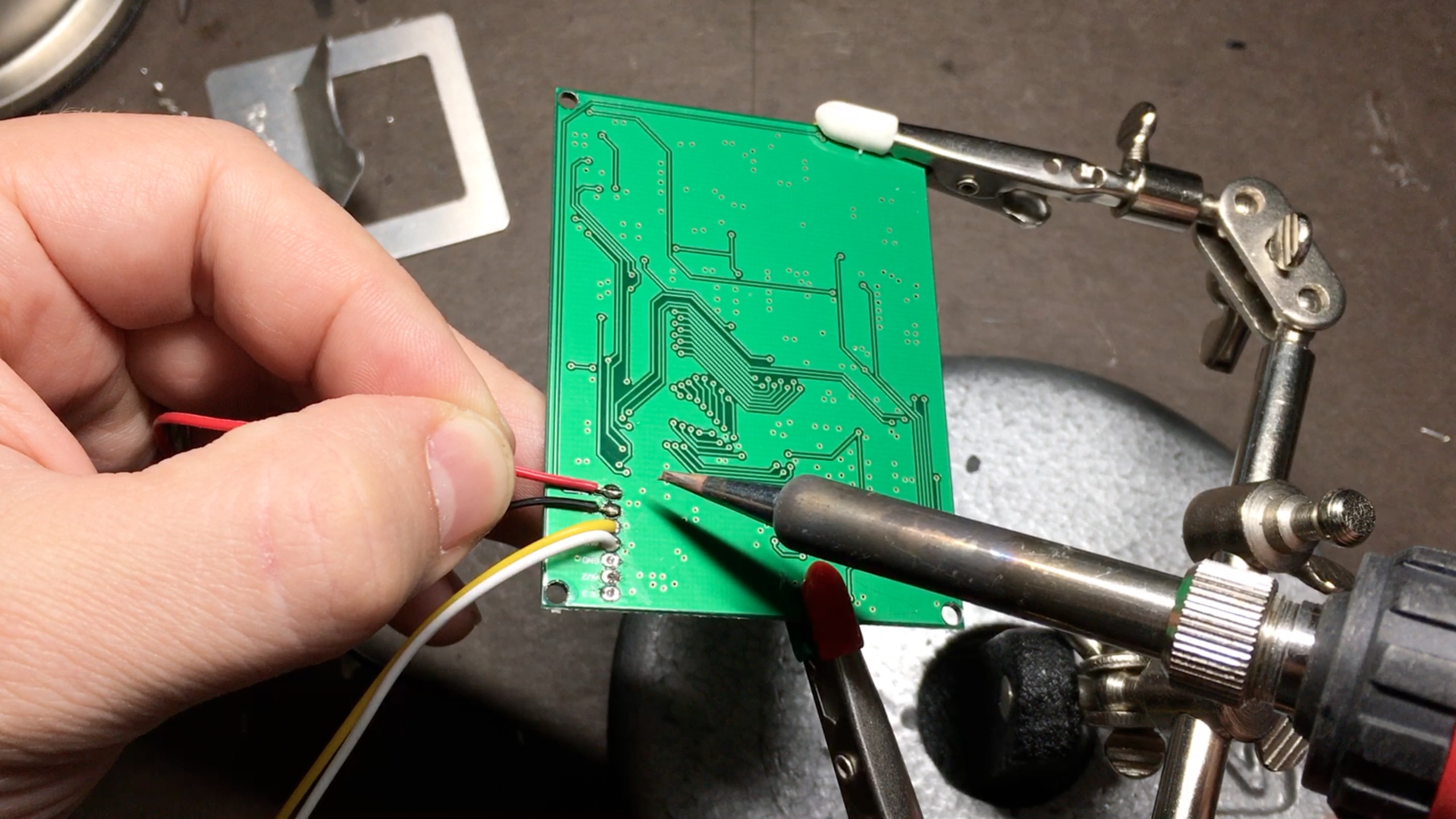
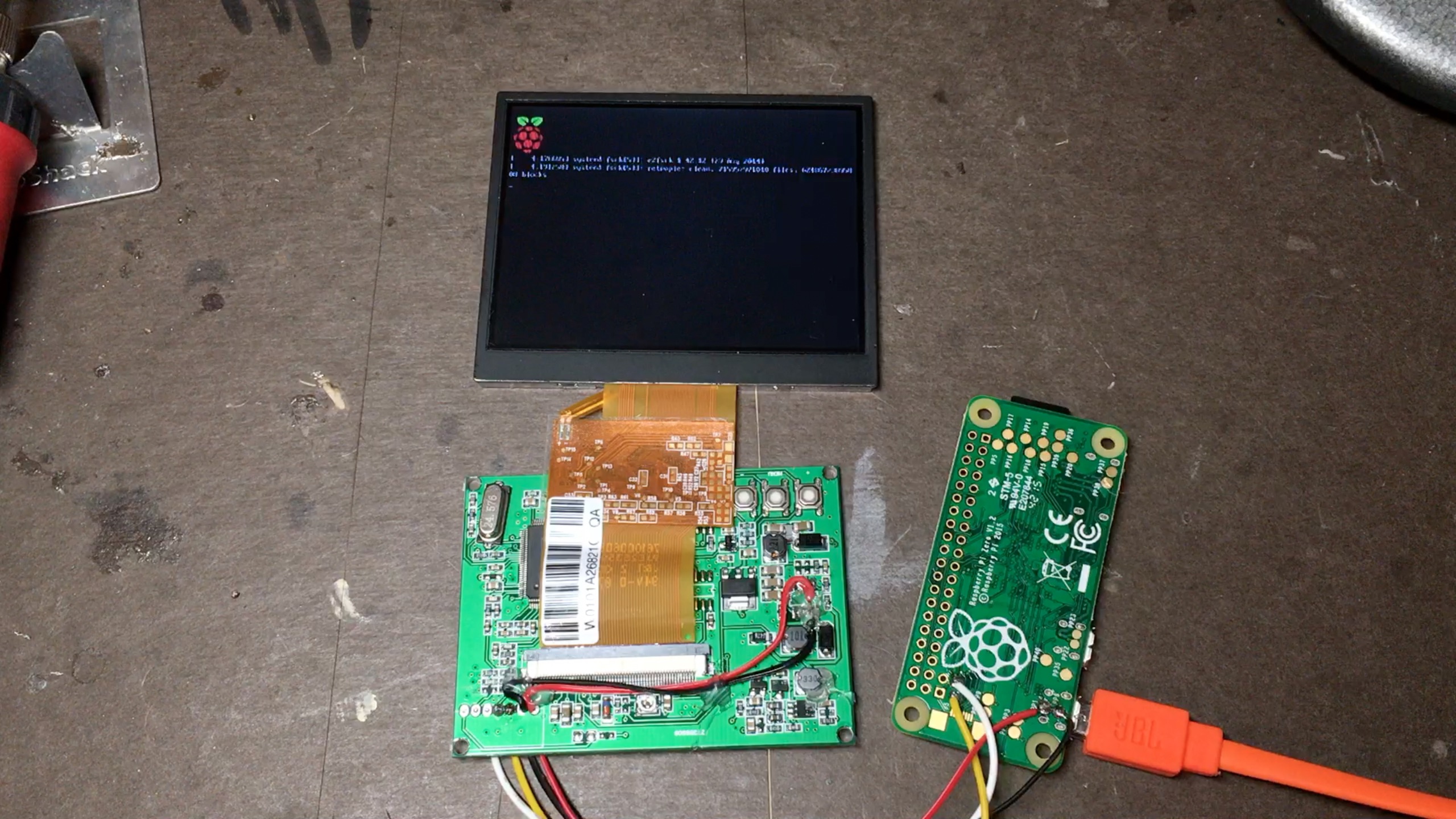
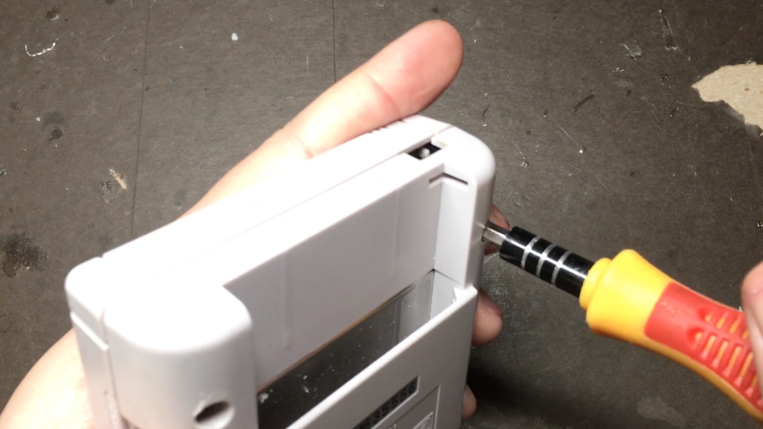
You can use the pads on the back of the Pi to do this. You’ll need to snip off the composite connector (or use a male connector that you snip the other end off to test it without voiding the warranty, if you jumped down here from the beginning of the guide). You can check out what all the pads on the bottom do here: http://hackers.gallery/841/misc/raspberry-pi-zero-pad-probing
The pad labeled PP1 is 5V, PP6 is ground, and then the pins for composite output are above PP4 and PP9 (the actual video output ones aren’t pads and aren’t labeled). The pin above PP9 goes to the white wire, the pin above PP4 goes to the yellow wire.

To get a picture out of it, you need an SD card inserted into the pi with an OS on it. This can be vanilla Raspbian, or Retropie if you like. Just be sure to download the one for the Pi Zero if you go with Retropie. You can either follow the official instructions for writing the OS image (the .img file) to an SD card, or you can use an awesome tool called Etcher to do it in a few clicks (it has Mac, Windows and Linux versions). All you do is put your SD card in an adaptor and connect it to your computer, load up Etcher and select your OS .img file you downloaded, select the SD card drive, and press “Flash!”
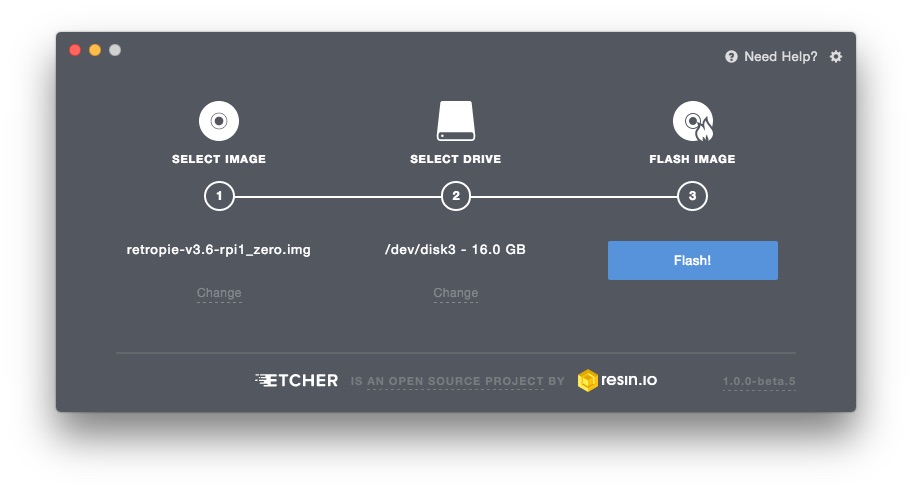
I’ve only tried it on a Mac but it looks to be pretty much exactly the same on Windows/Linux. Once it’s done, pop the SD card into your Pi, and plug your Pi into some power! Double-check your connections first to make sure nothing will short with the power connections you soldered to PP1 and PP6. Hopefully you see something similar to this:
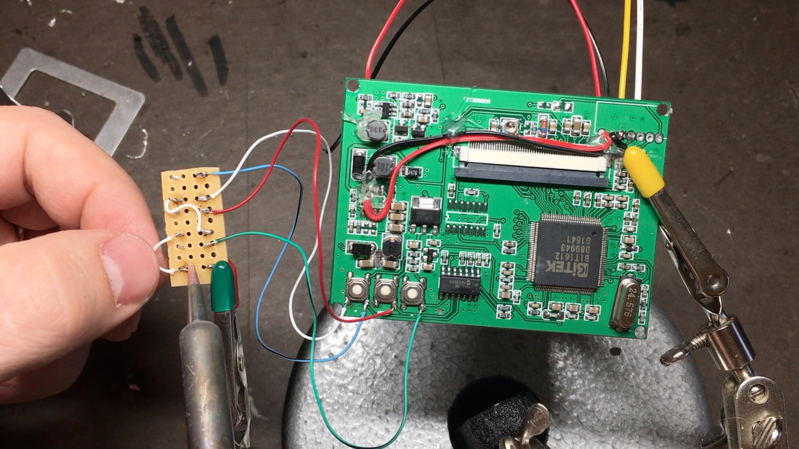
Once we are finished with this project and put it all together, we won’t be able to reach the brightness/contrast buttons anymore (if you don’t care about that then you can skip ahead). To fix this I made a little breakout board sort of thing (I’m not even sure that’s the right word but that’s what I’m going with), using a little piece of perf board and 3 tactile switches. If you don’t have any perf board you can just flatten out the pins on the tactile switches and glue them down to a small piece of plastic or something.
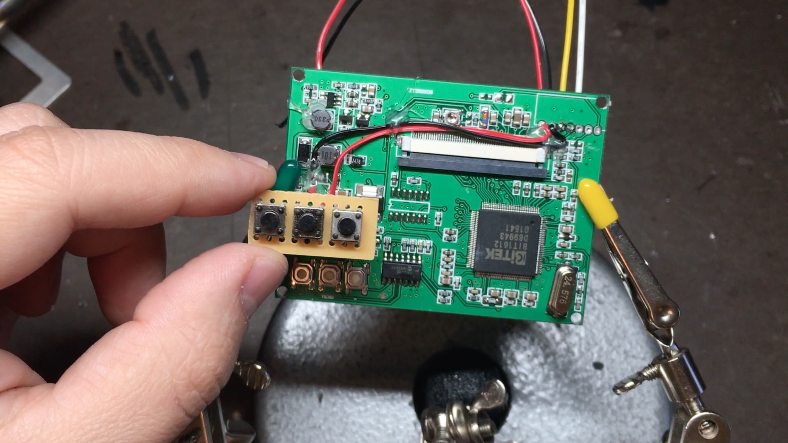
We’re going to wire up the pins on the board we are making to the pins on the actual buttons so when we push a button on the board in the battery compartment, it’s as if we pushed a button directly on the screen’s controller board. The bottom left pin on the actual buttons on the green board (from this angle, anyway) are ground, and they are connected so we only need to tap into one of them. Then we just need to wire up 3 more wires to the bottom-right of each button.
From the way I’m holding the breakout board above, the 2 pins on either side of the tactile switches are connected, so you can wire up to either one of them. One side will go to ground, the other side will go to one of the 3 other wires. You’ll notice in the image below that I only wire up the ground pin of one of the actual buttons to one pin on the breakout board. Then I use the other pin on the same side to link up to a pin on the next button over. That might sound confusing… Watching the video will probably help a lot with this part.
When you’re all done you can test that the buttons work by using a volt meter (like I showed in the last guide) connected to the “real” button pins on the green board, and making sure resistance drops to 0 when you push the corresponding button on the breakout board. You could also test by reconnecting the screen to the board, turning on your Pi again and making sure the buttons control it. After you’re sure it works, lay down a little hot glue to keep those connections from breaking.

Now to mount the screen. If you hold the screen inside the case you’ll see that there is some bare metal showing from the screen’s bezel. You can either cover this with electrical tape or mask off everything but the bezel (including the ribbon cable!) and spray paint it. I found that the Adafruit screen actually came with a screen protector out of the box that nearly perfectly masked off everything for me already, so I just masked off the ribbon cable and took some flat black Rustoleum to it. Worked great! You can see it after painting in the image above.
Getting the screen positioned properly and level is the hardest part of getting it mounted. I found it easiest to hold it in there with my index finger pressing from the back, position it from the front, and gently set it face-down without shifting the screen.

You may need to position the screen slightly off-center vertically to keep it from bumping up against the button holes. Once it’s positioned, put a few small dots of hot-glue down to hold it in place. Double-check the positioning from the front, and put the rest of the glue down:

If you’ve been following along, you have probably noticed that I love hot glue. It’s a little messy, sure; but it’s fast, strong, cheap, and easy to cut/remove if you decide you need to move something. So I’m a fan.
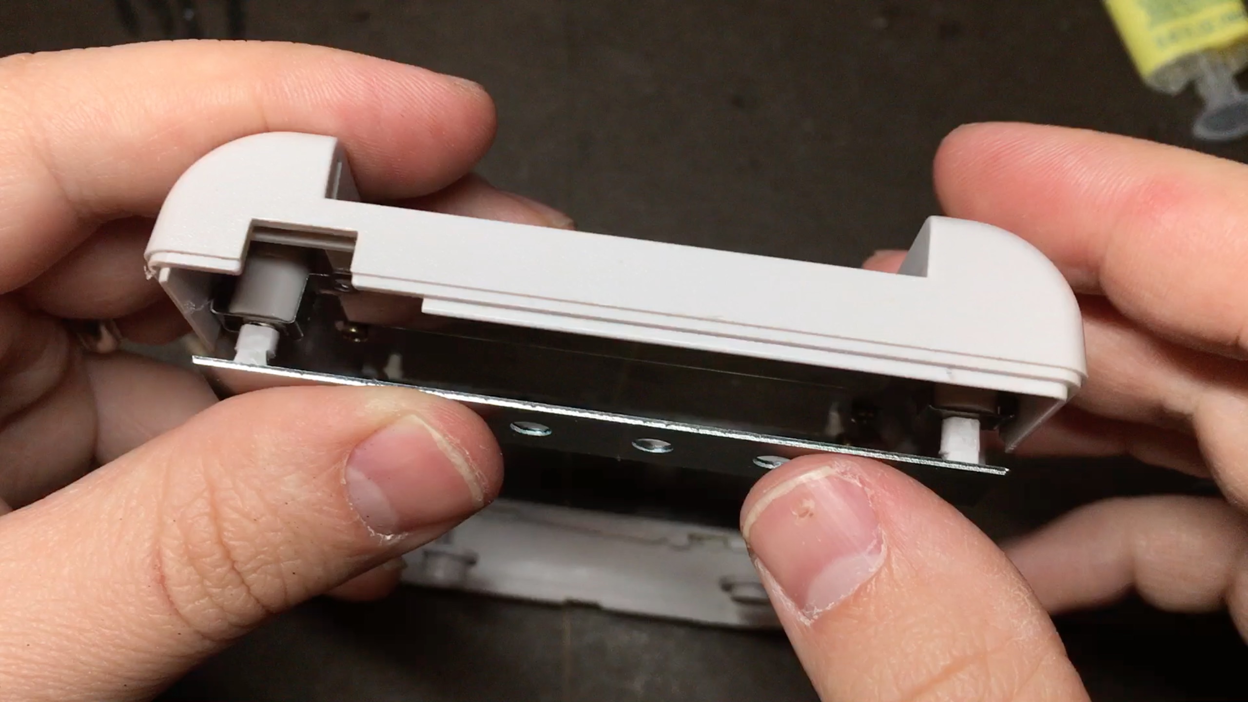
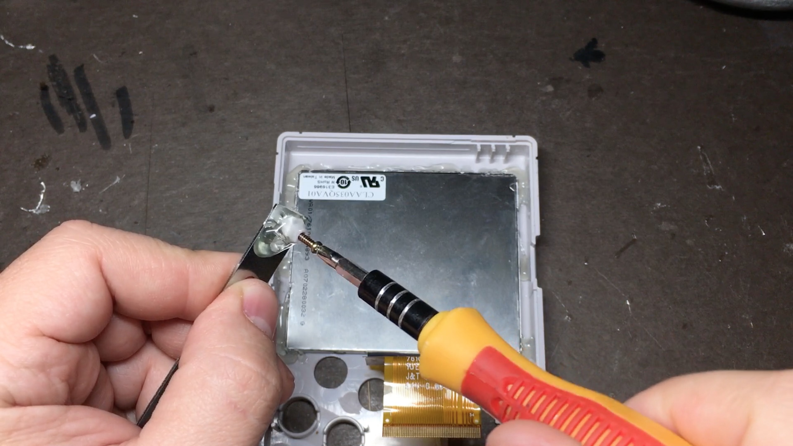
One thing I had noticed (and disliked) about nearly all the Raspberry Pi Game Boy builds I had seen is that they didn’t really have a good solution for putting the case back together. I even saw some taped together. ಠ_ಠ We can do better! Now that the screen’s in there we are going to make the top-rear screw holes usable again. To do this we are going to create a bracket that has the original screw posts attached to it. Take a strip of metal or some other strong, rigid material, and cut it to 82-84mm in length:

I got the metal strip I used from a home improvement store from their misc. mounting hardware area. I like that it has the holes in the middle which let me lay glue down in them. Mark two dots on it that are exactly 74mm apart, equidistant from the edges (this is the center-to-center distance of the screw holes).
Now cut the screw posts to be about 6mm tall. Shave some plastic off either side (but not too much!) so that it is pill-shaped and cut a small notch in both sides that you did not shave from. This will make them much more resistant to turning and coming loose when you put a screw in there, and more resistant to being pulled out. This is why I told you to save all 4 you removed in part 1: in case you happen to mess up one of these ones. 🙂

Put a very thin layer of hot glue down and stick the screw posts to the dots you put on your bracket (if you put too thick a layer down it will get pressed up into the screw hole and make it so your screws can’t go all the way in). Now hold it up to the back screw holes of the case and make sure that they line up. It’s fine if the metal strip isn’t perfectly level – all we care about is the holes lining up.
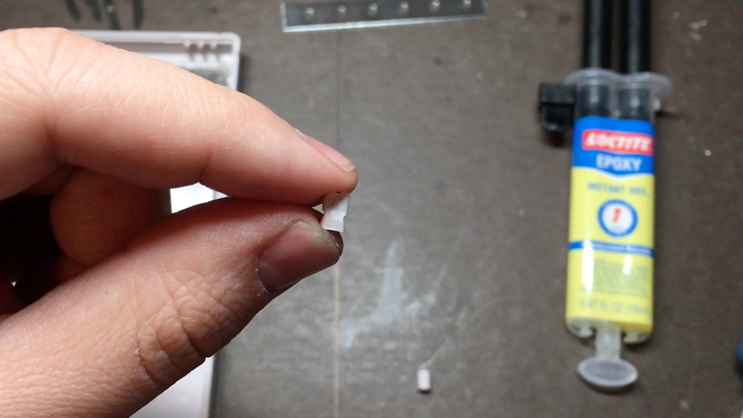
If that checks out, then bring out the epoxy so we can make these things permanent! It’s helpful to get some epoxy that has a mixing nozzle on it (so it mixes the two tubes for you as you squeeze it out). I used Loctite Instant Mix epoxy. I just made circles around each post and let it pile up. Be very careful to not get any in the actual screw hole. You may need to make another pass as it thickens a bit to let it pile up close to the rim of the screw post (it will be pretty runny at first but will quickly become thicker).
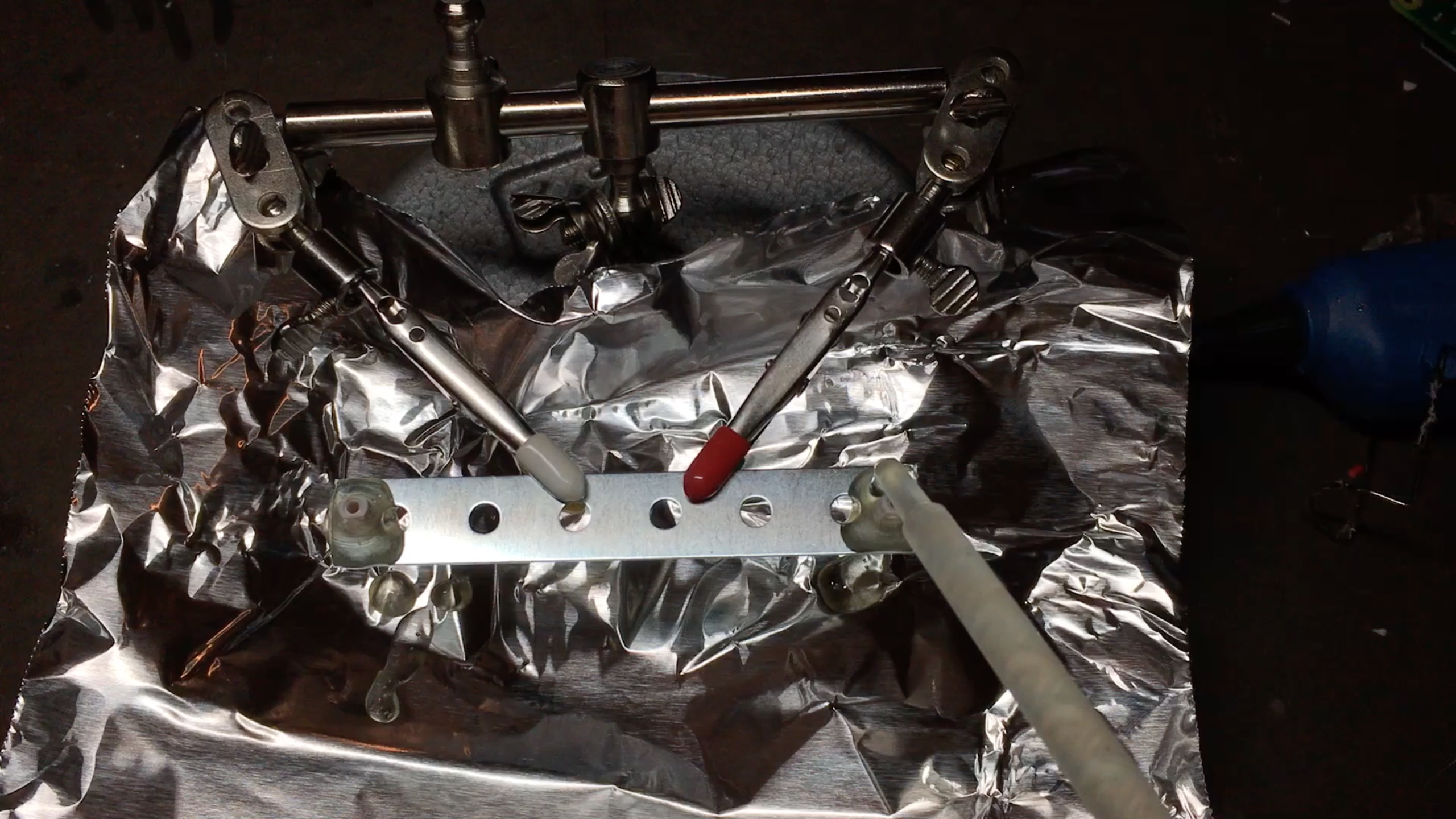
After 24 hours or so, it should be rock-hard and ready to try out. Slowly and gently start to put a screw into it. If you see the screw post moving at all, STOP! Let it cure some more and try again later.
If that checks out then it’s time to mount it in the case behind the screen! Lay your case down and set the bracket on top of it in about the location they should go. Place the back of the case on it, look down the screw holes from the back and see if it all lines up. Take the back off, adjust and repeat until they line up as perfectly as you possibly can get it.

Next put a few small dots of glue down, just enough to hold it in place while you put the rest of the glue down. Once those cool, put the back of the case back on and double-check that the screw holes and screw posts are still perfectly aligned. If so, then lay down the rest of the glue. I made sure to squeeze some into the gaps between the screen and the side of the case too, in addition to every edge:

It may be messy but it works great! After that cools down fully, put the back on it and feel the satisfaction of putting the original screws in the original screw holes and screw posts. Ahhhh, feels nice right?
That’s it for this part! Next time we’ll be mounting several components including the buttons/controller board, the composite display controller board, speaker, amplifier, headphone jack, on/off switch, micro USB charging port and external USB port, and L/R buttons.
We’re getting close!
Again, if you get stuck or need help with anything, stop by the forums! Tons of nice people on there sharing ideas, tips, suggestions, etc.
Be sure to enter to win the one I’m making in these guides below!
[rf_contest contest=’2000′]