We’re getting so close to the end! This time we’ll be creating the cartridge SD Card reader, and making a low-pass filter to use PWM audio from a GPIO pin.
The cartridge reader is probably the part of the project I get asked about the most. So just to clear a few things up: basically all we are doing is extending the existing SD card slot on the Raspberry Pi and running it through a game cartridge and the cartridge reader from the Game Boy.
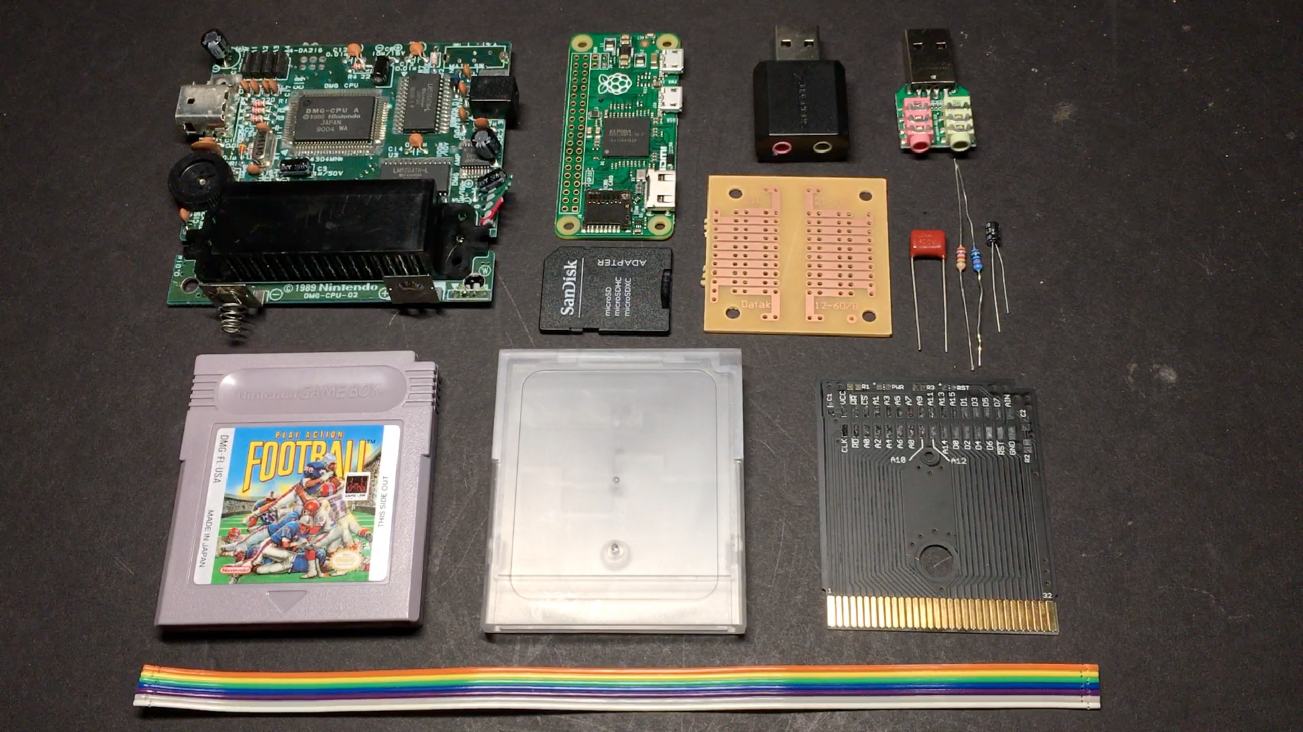
What we’ll do is desolder everything from an existing game, and connect an SD card to micro SD card adaptor to the pins on the cartridge. Then we’ll cut the cartridge reader off of the GB motherboard, and wire that up to the SD card test pads on the back of the Pi.
Before we start ripping apart a game, though, I should mention a few options you have. The website kitsch-bent sells a couple of things that could make this much easier for you: a blank GB cartridge board (which saves you from having to desolder anything and gives you nice big clean pads to solder onto), and a cartridge that has the SD card slot already on it (which saves you even more work). They also sell empty cartridge shells, which will save you from needing a GB game at all, which is nice.

Also, forum member prerunnerseth has a custom cartridge PCB that he’s designed as well. His is nice because it has a capacitor on it that can help remove some potential noise/interference from the SD card reader (more on that later) and from what I understand he is working on an updated version with even more filtering which should make it much easier to get going and make it more reliable. So definitely keep an eye on his thread!

Once you’ve picked the game you intend to use (please pick something nobody cares too much about! Leave Metroid 2 and other classics alone… 😉 ), you’ll need a special tool to open it up. I have a screwdriver bit like the one below, which isn’t really made for this type of screw, but it works. If you don’t have anything that will work, kitsch-bent has you covered.

Desolder everything from the board, as we’ve done in the past with other things, and clean up with a desoldering braid when you’re done.


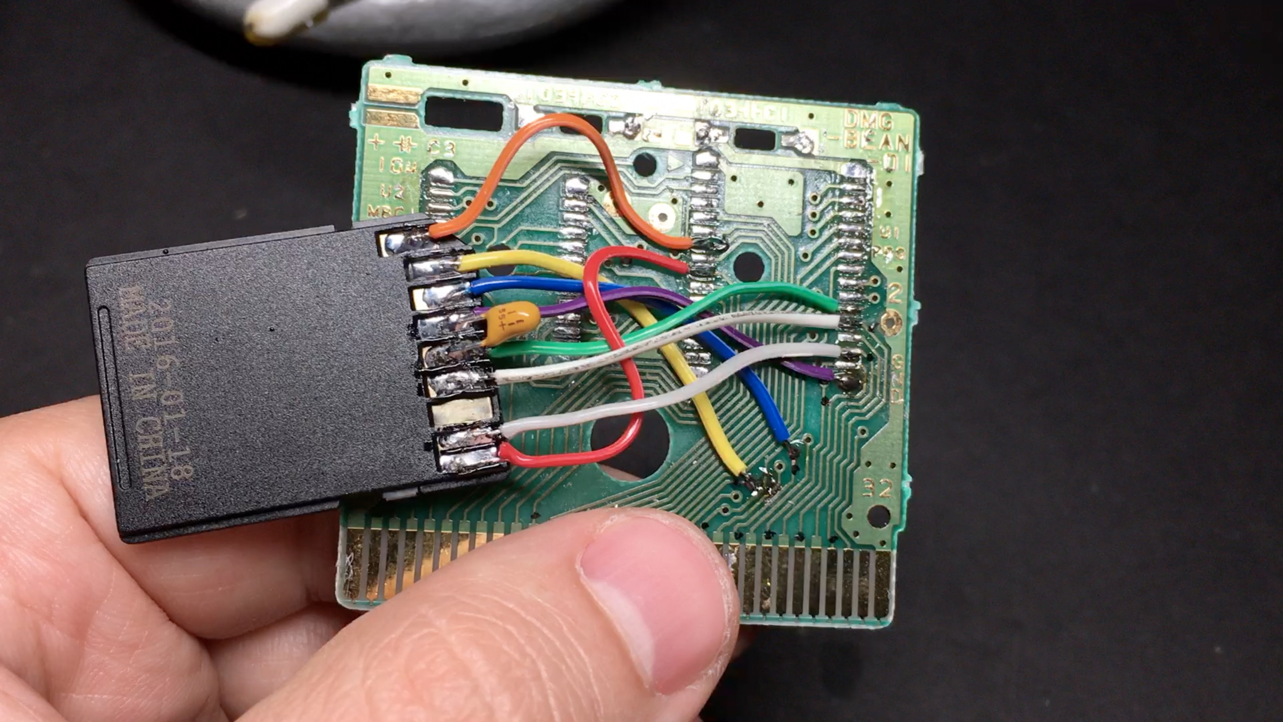
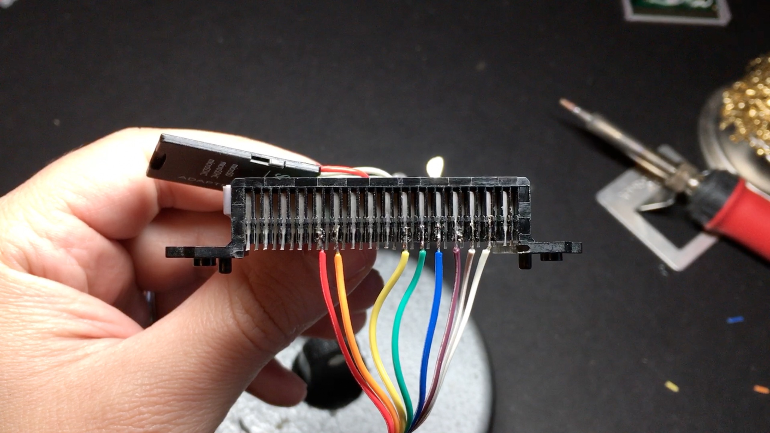
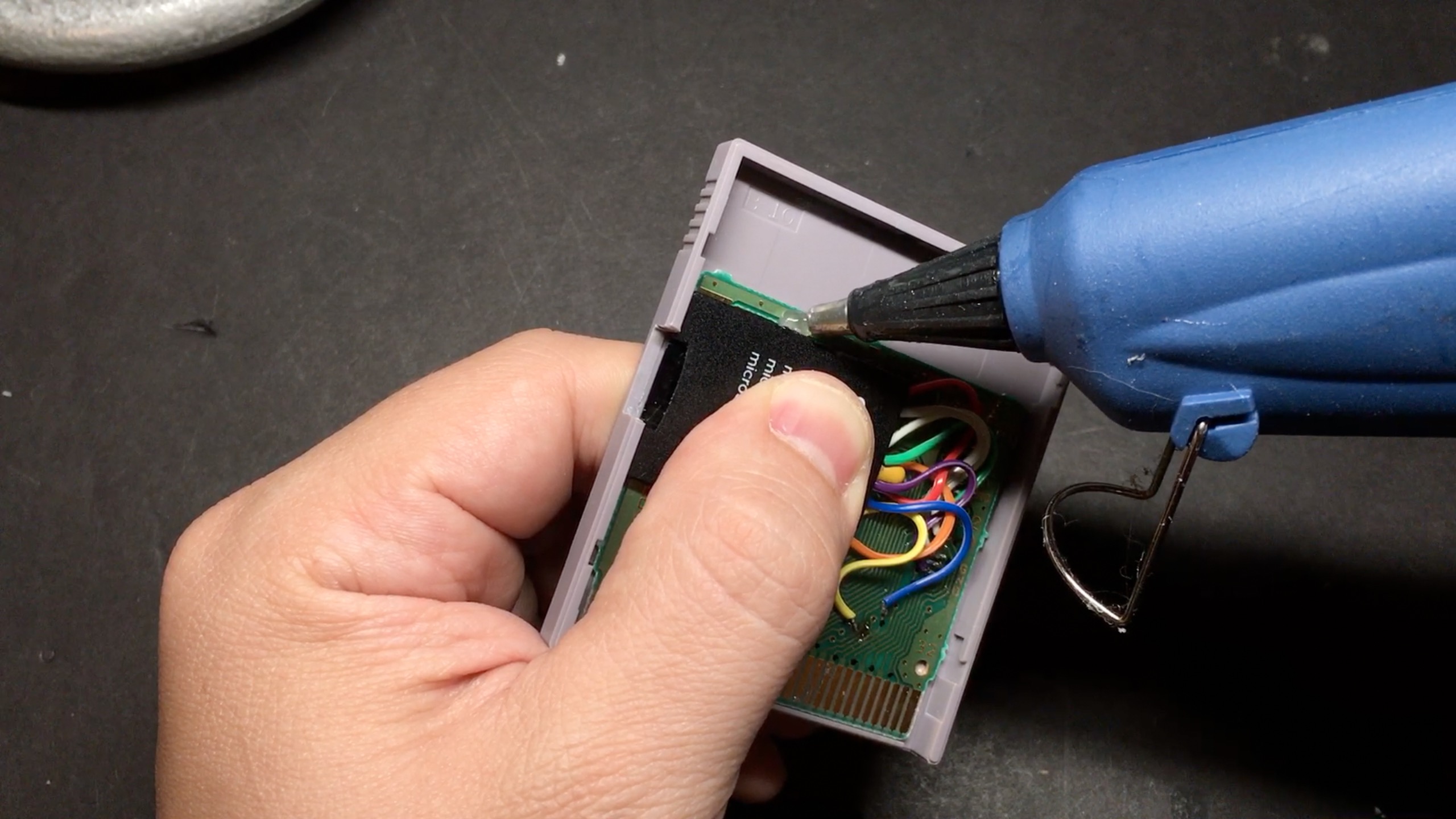
Now it doesn’t really matter too much which pins you use, but I do recommend that you don’t use adjacent pins if at all possible, and use odd-numbered pins (when counting from the left). This will make it much easier to solder wires to the cartridge reader. Use thin wire, preferably of different colors (“preferably is putting it lightly – this is almost mandatory with how much easier it makes it) so they are easy to differentiate. You’ll need 8 wires/pins (the full-size SD card has 9 pins, but two of them are ground, and we only need one of those). The picture below only has 7 wires because I forgot the 8th wire at first. 😐

Below is a pinout of a full-sized SD card (I grabbed this image from google image search, and the same image showed up on tons of sites so honestly I’m not sure who to credit). We’ll be using all the pins except VSS2, which is pin 6. VSS1 and VSS2 are ground. Make a note of which SD card pin goes to which color (taking a picture when you finish soldering them all up helps).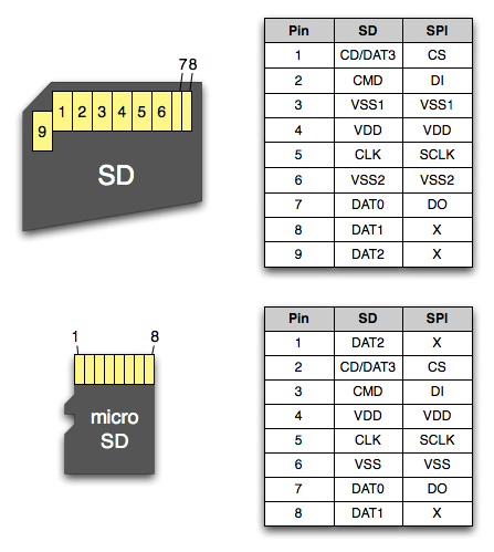
From talking to prerunnerseth on the forums, it’s a good idea to put a capacitor on the 3.3v pin (VDD, which is pin 4). I used a 1.0uF capacitor and put the positive leg on pin 4, and the ground leg on pin 3. If your capacitor has uneven legs, the longer one should be positive. If they are the same length, it doesn’t matter which way you put it in.
A capacitor used in this way is called a decoupling capacitor. In a nutshell, it will help to sort of absorb some noise that could be introduced into the rest of the circuit by the 3.3v line (pin 4). It should help the reader be more reliable.
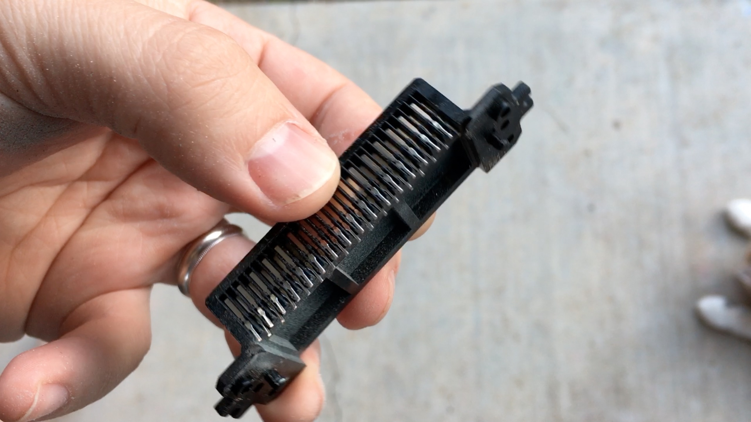
Now remove the cartridge reader from the GB motherboard. The easiest way to do this, I’ve found, is to just take a circular cutting bit on your dremel and cut the pins flush with the board:

You can count pins to figure out which pins in your cartridge correspond to which pins on the reader, but I find it easier to just insert the cartridge and use a multimeter to check continuity to figure out which SD card pin goes to which cartridge reader pin:

As you figure out which pin goes where, connect a 6-inch or so piece of wire of the same color to each cartridge reader pin. This is why I recommend starting on odd pins in the cartridge, and using every other pin: it will let you solder to just the outside pins, which is much easier. 🙂
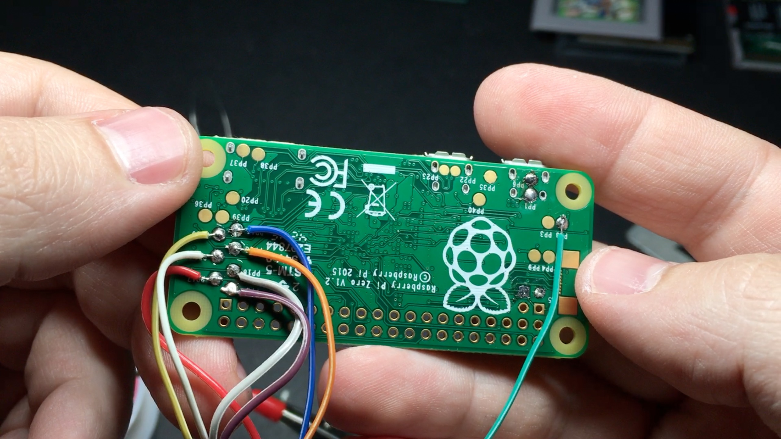
When you’re done with that, it’s time to connect the other end of your cable to the Pi itself. If you look at the back of the Pi around the area where the SD card reader is, you’ll see a cluster of test pads. You can reference the chart below, as well as the SD card pinout chart above, to find which wire goes where (chart taken from this site):
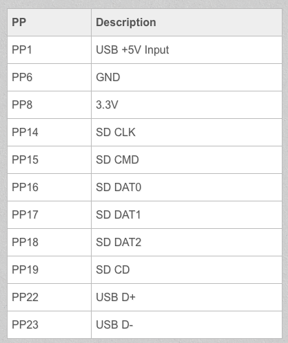
Pin 4 on the SD card (VDD) will go to the 3.3V pad on the Pi (PP8), which is at the other end of the board. The other ones are easy enough to match up by name. Starting from the left:
- Pin 9 goes to PP18
- Pin 1 goes to PP19
- Pin 2 goes to PP15
- Pin 3 goes to ground (PP6 is one option)
- Pin 4 goes to PP8
- Pin 5 goes to PP14
- Pin 7 goes to PP16
- Pin 8 goes to PP17
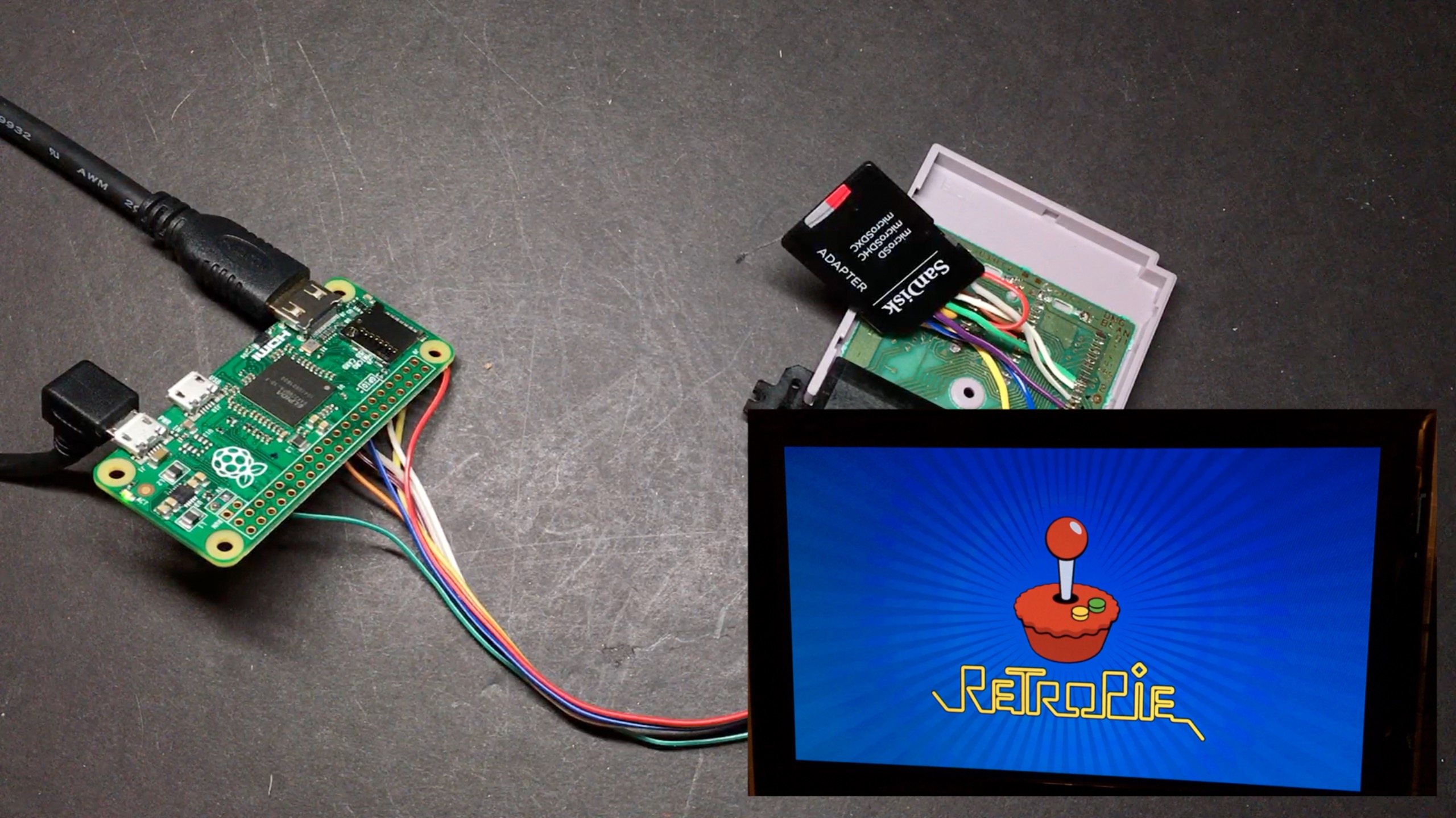
Double check your wiring a few times to make sure you don’t have any unintended shorts/bridges, and that everything is going where you think it should. If you’re pretty sure you’ve got it right, pop an SD card that has an OS loaded on it into your cartridge reader, and try it out! Hopefully it boots up for you.
Now, fair warning: In doing my first GBZ, and now this one, I’ve found that SD cards can be really finicky. For example I had two Sandisk Ultra 32GB Class 10 cards that I bought at the same time and are supposedly identical. One of them works fine with the reader I just made, one of them refuses to boot. Both of them work when inserted directly into the Pi, so I know it’s the reader causing the issue. I honestly don’t know what the deal is. It seems that some cards are just more tolerant of noise/interference than others.
If you run into that issue, I’d make sure that you have your wires as short as they can be (they need to extend from where the cartridge reader will be seated, to the other side of the case where the Pi will be), and also try adding some shielding (you can do this by just wrapping a strip of aluminum foil around the wires, along with a strip of electrical tape down it so that aluminum doesn’t touch anything conductive).
If you just cannot get it to work, I’d recommend either trying one of the pre-made cartridge solutions (like prerunnerseth’s upcoming board that will have some nice filtering built into it), or consider just going without it. Yes the cartridge is awesome and oozing with nostalgia, but it’s really not necessary to have a fully-functioning emulation handheld (you can just put the SD card in the pi itself), nor is it worth risking corrupting your SD card while using it if you can’t get it working rock-solid.
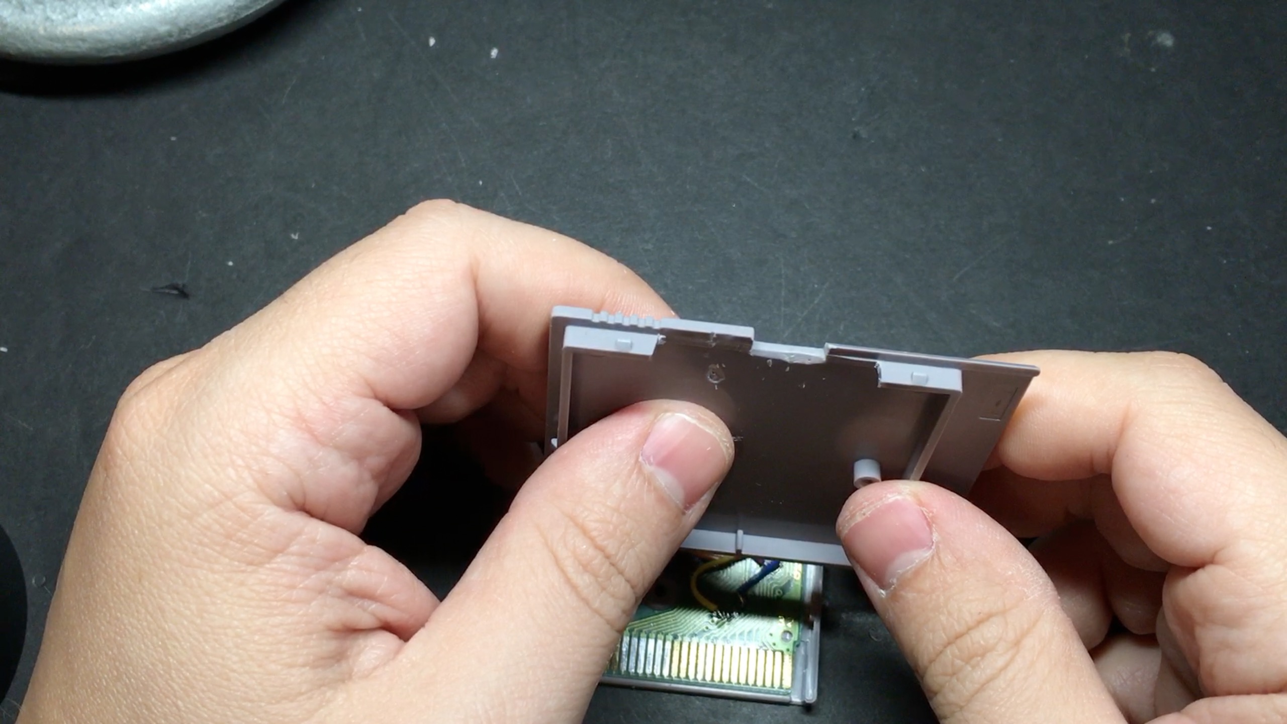
Before putting the cartridge back together, you’ll need to do a bit of cutting so that the SD card adaptor is accessible. Then glue down the SD card adaptor so it is flush with the edge of the cartridge (be careful not to glue it down to where the screw hole is obstructed). You should have a notch cut similar to the one below, depending how you positioned it.
Now you’ll need to shave off a good chunk of the lip on the front side of the cartridge, so that it can slide into place when you put it back together:
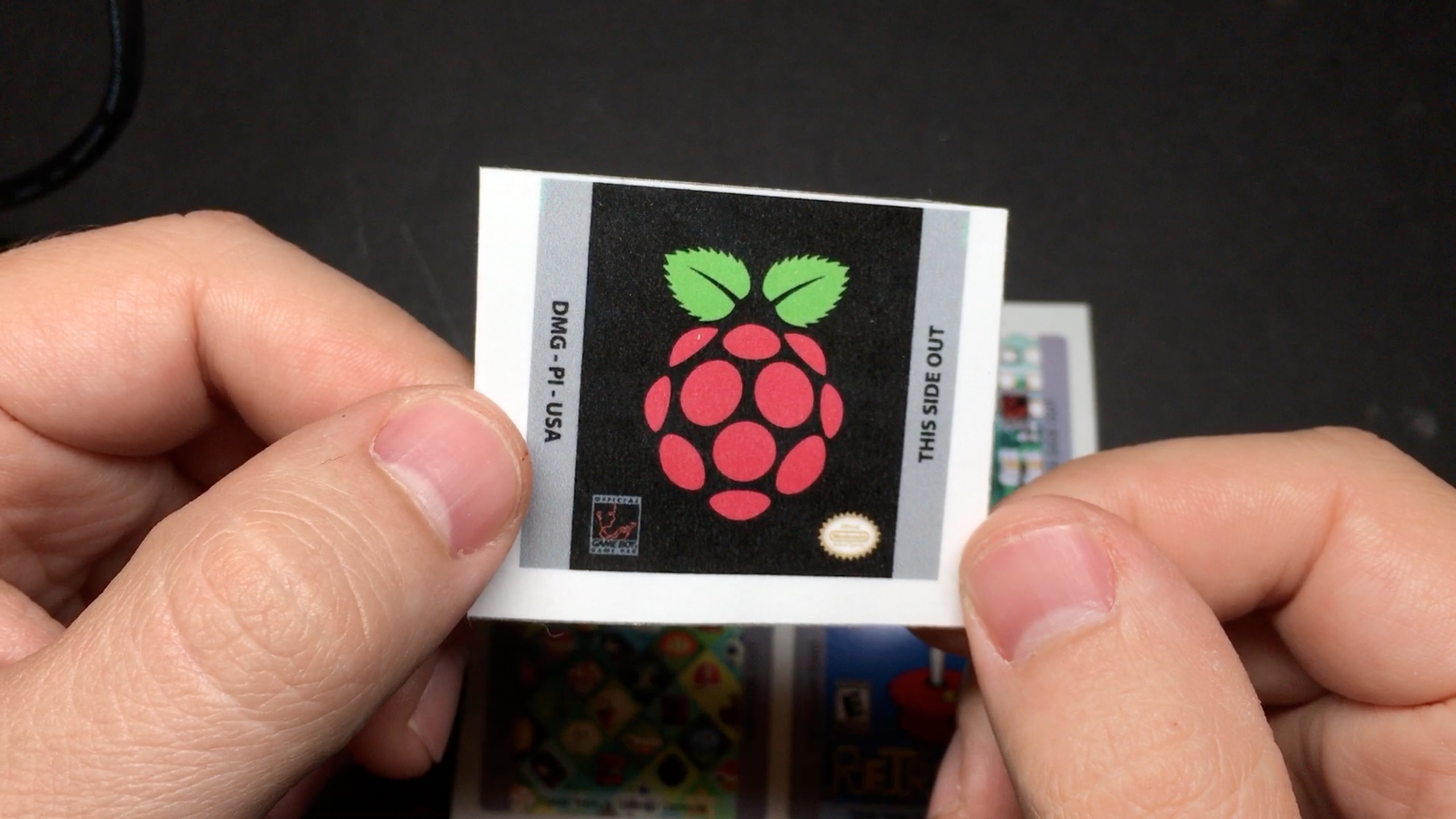
As for the cartridge label, I used this template from deviant art. I just plopped the Raspberry Pi logo from raspberrypi.org onto it, as well as a couple Nintendo GB seals. I printed it out on a sticker label from Avery. Here is my version that has the Raspberry Pi logo on it. Then I took a piece of packing tape and placed that on top of it, and took something like a credit card and rubbed the heck out of it so it was essentially laminated. Sounds sort of hacky, but it worked great! It gave it a nice glossy finish and honestly made it look close to factory-made.
A forum member user named dominator is also offering some custom labels for sale. They must have access to some pretty sweet professional printing equipment, because the ones they sent me are awesome:
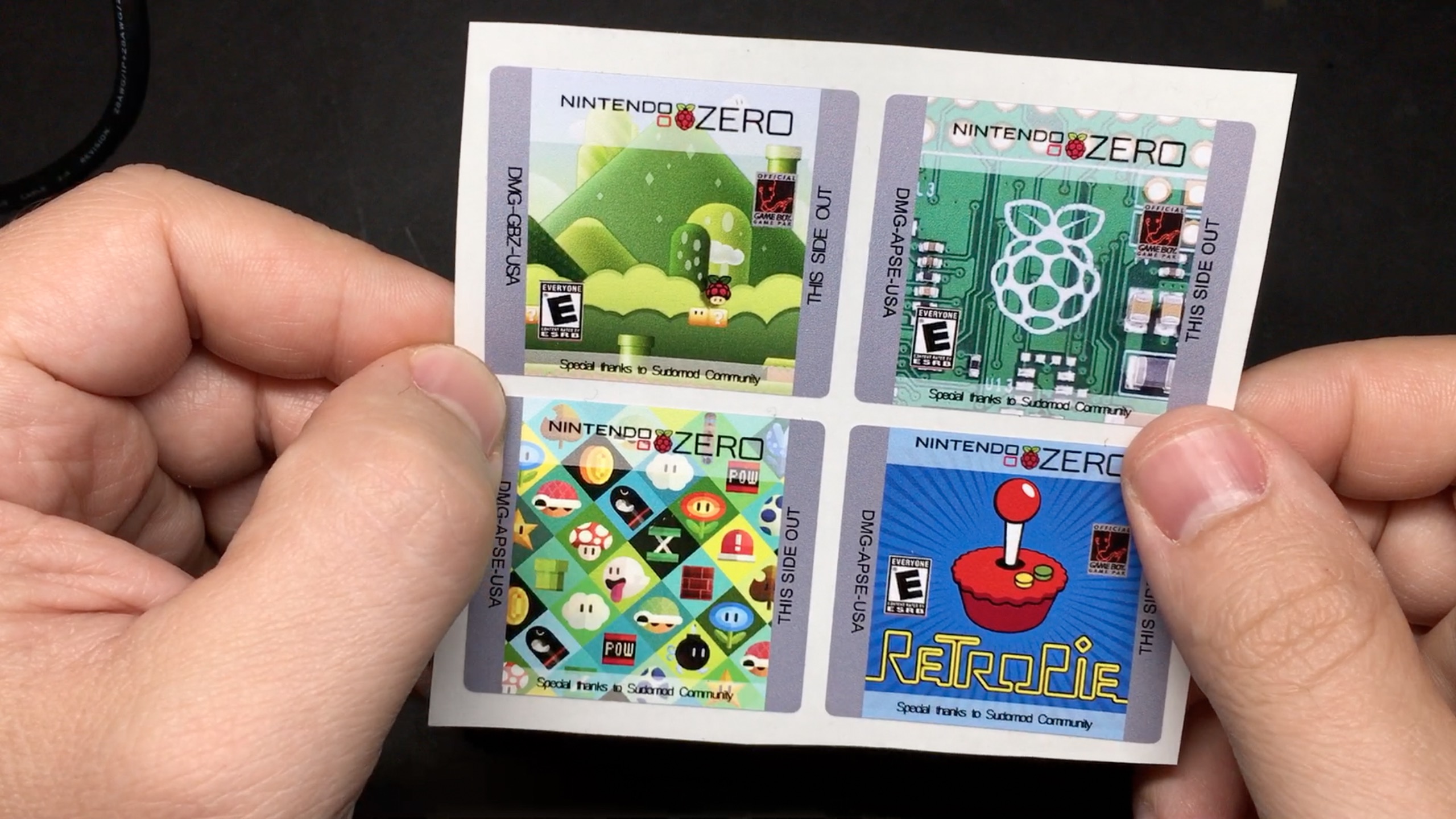
Big thanks to domintor for sending some over!

Now for audio output. Turning on audio output via GPIO is actually super simple. Pop the SD card you have RetroPie on into your computer, and open the file named “config.txt” with a text editor. At the end of that file, add this line:
dtoverlay=pwm,pin=18,func=2
That will turn GPIO pin 18 into audio output. Note that this is just for mono sound with one pin. If you are doing stereo sound through the headphone jack (I’m not), then you would want to add this line in stead:
dtoverlay=pwm-2chan,pin=18,func=2,pin2=13,func2=4
This will enable PWM audio output on GPIO pin 18 (or pins 18 and 13 if you are doing stereo). Pimoroni includes this handy chart with the GPIO pins labeled when you buy a Pi Zero from them:
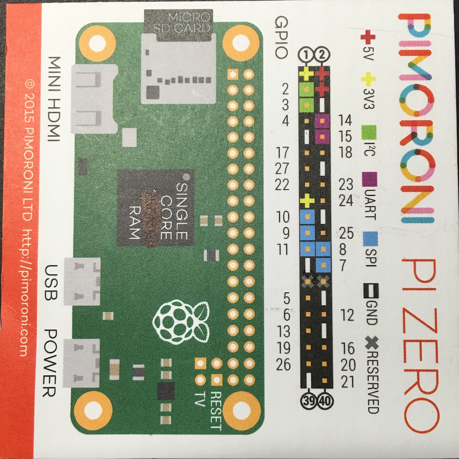
As you can see the GPIO pin number doesn’t necessarily correspond to the physical pin number.
That was easy, right? Well, we’re not quite done. 🙂 It’s not a good idea to feed the signal from that as-is to the amplifier. You should really run it through a low-pass filter first. Making one is pretty simple, and there are lots of guides for it. In fact there is a fantastic one on the forums by a user named SP33 that I highly recommend checking out (the diagram I’ll include below is from their guide). Adafruit has a guide as well, although their instructions for enabling PWM audio in the operating system is way more complex than it needs to be now-a-days; but the part of their guide for the hardware is still relevant.
You’ll need two resistors, and two capacitors:
- A 10uF electrolytic capacitor
- a 33nF ceramic capacitor (if you can’t find 33nF, then 10nF will work fine as well)
- a 150 Ohm resistor
- a 270 Ohm resistor
Using a prototyping board, arrange them like so (thanks to SP33 on the forums for the diagram!):
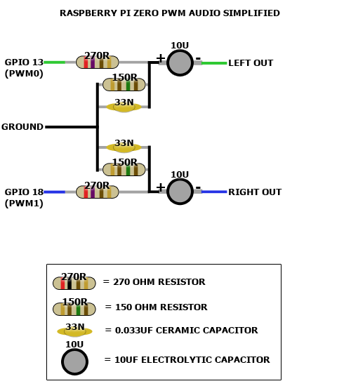
If you are doing mono sound for the headphone jack/speaker like I am, you only need to do the bottom half of it. It should look something like this:
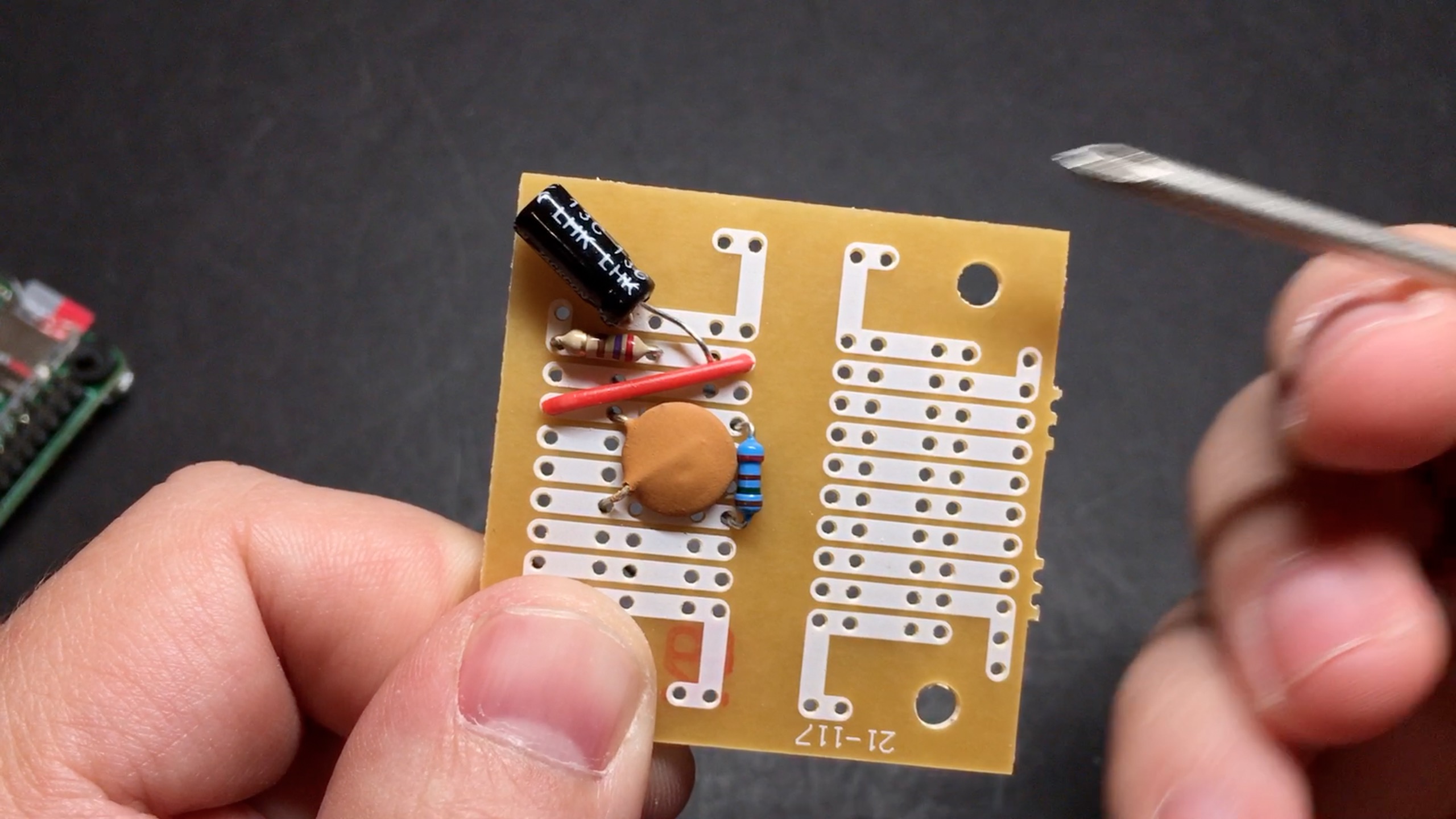
You’ll want to cut the copper trace on the back-side between the two ends of the 270Ohm resistor.
It’s probably easier to just watch the video at the top of the guide where I show you which pin is ground, input, and output.
Once you have that made, cut it down to size and try it out! You can connect it to GPIO pin 18 and ground on the Pi, and connect the output to the input on your amplifier. I tested mine in a breadboard setup, but you can use your already-mounted amplifier/speaker setup from the previous guide too. The amp needs 5V, which you can get from pad PP1 on the bottom of the Pi (PP6 right next to it is ground). The purple wire in my test setup below is the GPIO pin that is sending audio, and the white wire is ground (orange/grey are power).

Launch something that produces some sound (I used Quake from the “Ports” menu in RetroPie), and hopefully you hear something.
Another popular option is USB sound. I haven’t tried this yet myself, but I know there are lots of forum users who prefer it. Some USB sound cards even put out enough power to make the separate amplifier board unnecessary. The one everyone seems to be using is from Sabrent, and it looks like this when you take the case off:
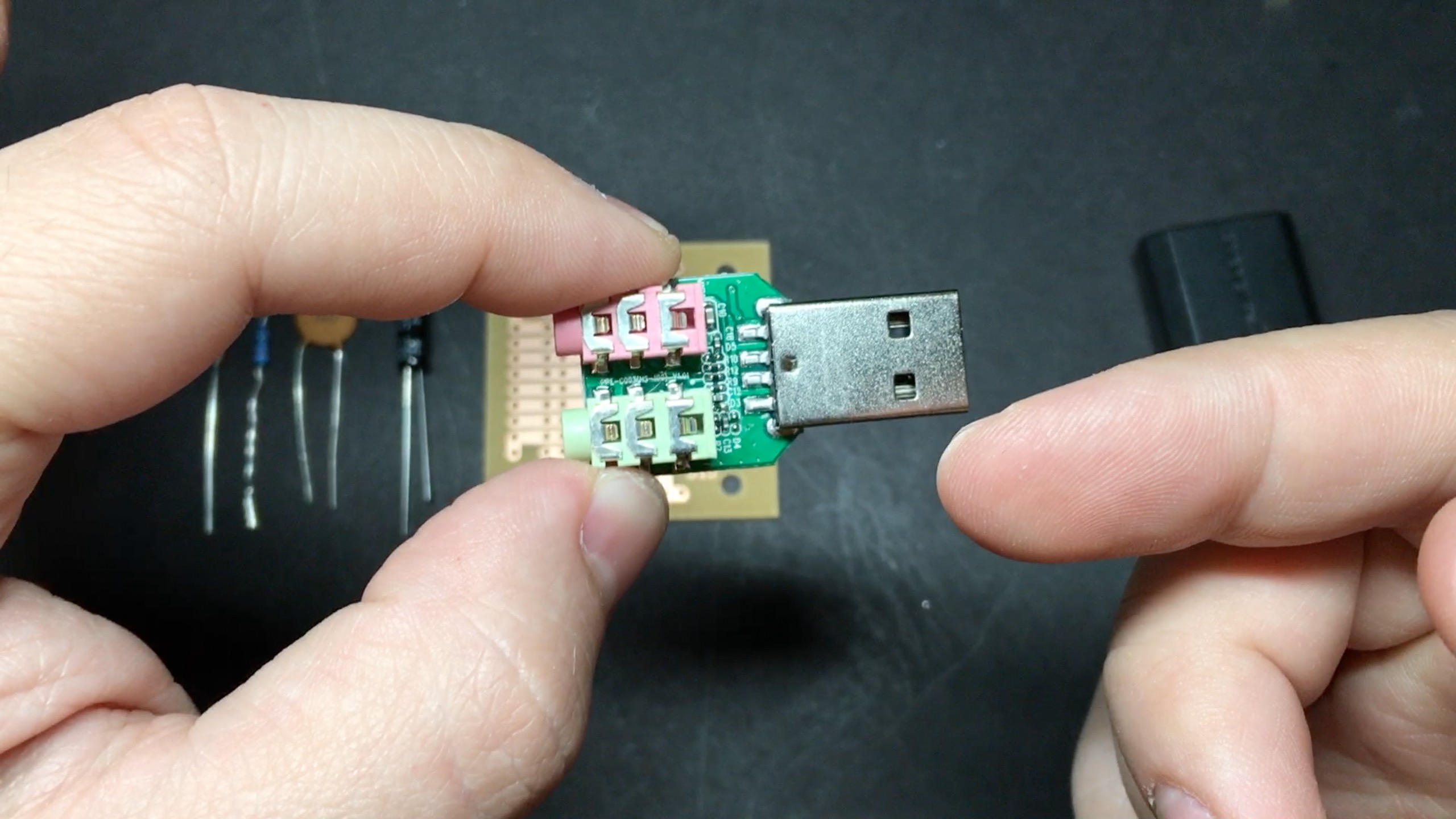
You can desolder the 3.5mm jacks, as well as the USB plug, and have a board that is much smaller than the hand-made low-pass filter board. Kilren on the forums has a fantastic guide for using the Sabrent sound card, so if you would rather go the USB sound route, I’ll refer you to his thread. Thanks, Kilren!
That’s it for this time! I think we can squeeze the rest of this build into one more guide, so keep an eye out for that soon!
Be sure to enter below for a chance to win the Game Boy Zero that I’ve been building throughout these guides!
[rf_contest contest=’2000′]