Welcome back to the 6th and FINAL installment of the Game Boy Zero guide!
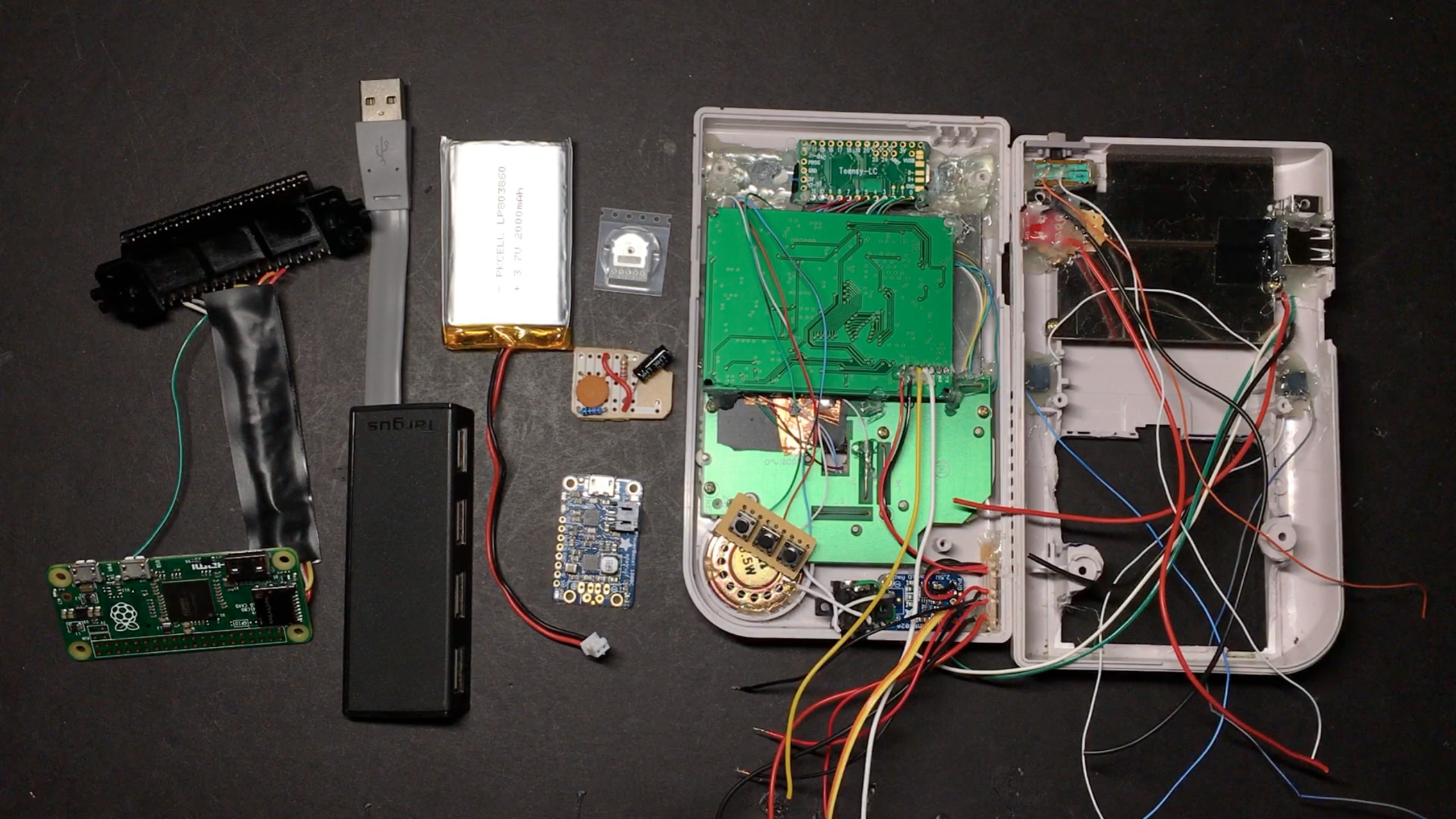
Today we’ll be wrapping up all the remaining items. This includes:
- Wiring up the Powerboost
- Adding a USB hub
- Mounting the Pi and cartridge reader
- Adding a volume wheel
- Cleaning up and connecting all the remaining wires (screen, sound, L/R buttons, etc)
Hopefully after this, you’ll have yourself a working Game Boy Zero build!
The power boost is awesome because it does two things: it charges the battery, and it also converts the 3.7v from the LiPo battery into 5v for us to power our Pi, Teensy, etc. with. Everything you could ever want to know about it can be found over on Adafruit.
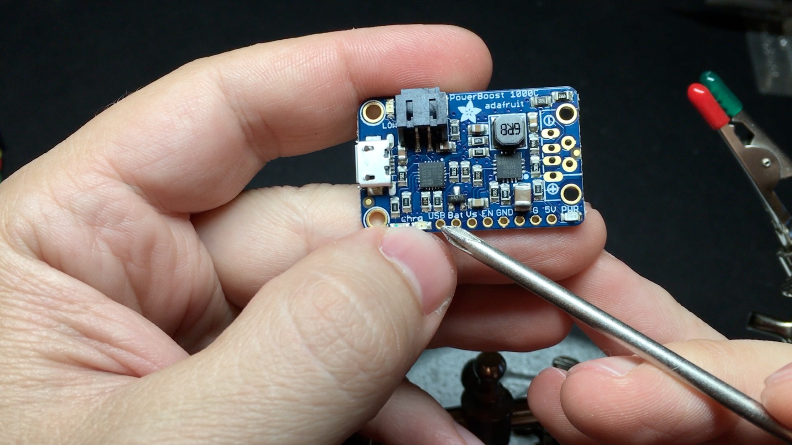
There are several pins at the bottom. We’ll be connecting:
- The micro USB charging port to the USB pin ground (GND)
- The power switch to the enable pin (EN) and ground (G)
And then where the output USB port would have been soldered, we will connect the power wires for the external USB port, and the power strip we made.
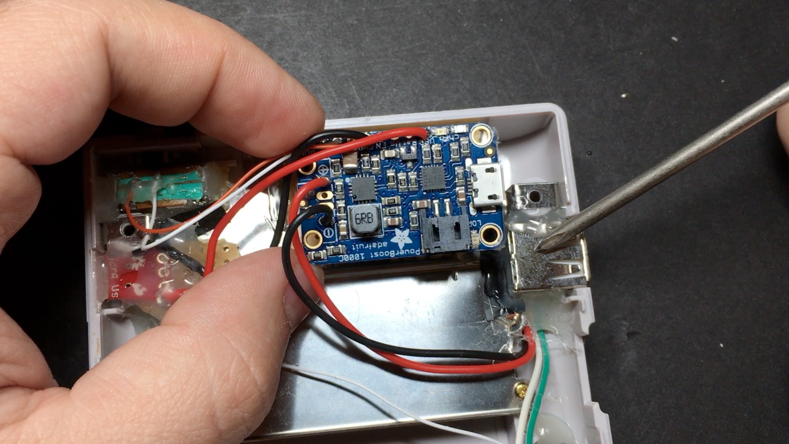
I placed my Powerboost differently this time around. In my first one it was just kind of hanging around in the battery compartment, not mounted to anything. I hated that, so this time I’m mounting it in the empty space up towards the top of the case:

You definitely want to make sure the board can’t come in contact with the metal shielding plate. With something this potentially dangerous, I didn’t trust a simple strip of electrical tape; I used a small piece of perfboard underneath it. Just make sure you mount it far enough to the right that the battery connector won’t hit the Teensy on the other side of the case. The Powerboost can get pretty toasty, so if you use hot glue only use it on the corners.
Before actually connecting any wires, it’s a good idea to double-check the wires for your micro USB charging, external USB, and power switch. Check on your multimeter to make sure none of them are shorted and that the power switch behaves as you are expecting (when the switch is pushed to the left from this perspective, the wires coming from the power switch should have continuity so that they put the enable pin to ground, and shut everything down).
Once you’ve double-checked all that, go ahead and trim your wires and hook it all up. Here’s about what it should look like after you mount it and wire up everything as described above:
For testing, first just connect a micro USB cord without a battery and make sure it turns on with the switch. If that seems to work, unplug the USB cable and plug in the battery and test the switch.
WARNING: LiPoly/LiIon batteries are dangerous. Make sure you don’t break the outer seal, bend it, crush it, let it press up against something hot, etc. And absolutely make sure the wires coming out of it never touch each other. If you’ve never messed with batteries like this before, consider finding someone who has to help you out. Proceed at your own risk!
If all that checks out then plug in the USB cable and make sure that it charges the battery.

Now for the USB hub. I used one I had laying around from Targus. Pretty much any USB 2.0 hub will work (for cheaper than the Targus), as long as it’s small enough to actually fit in the case.
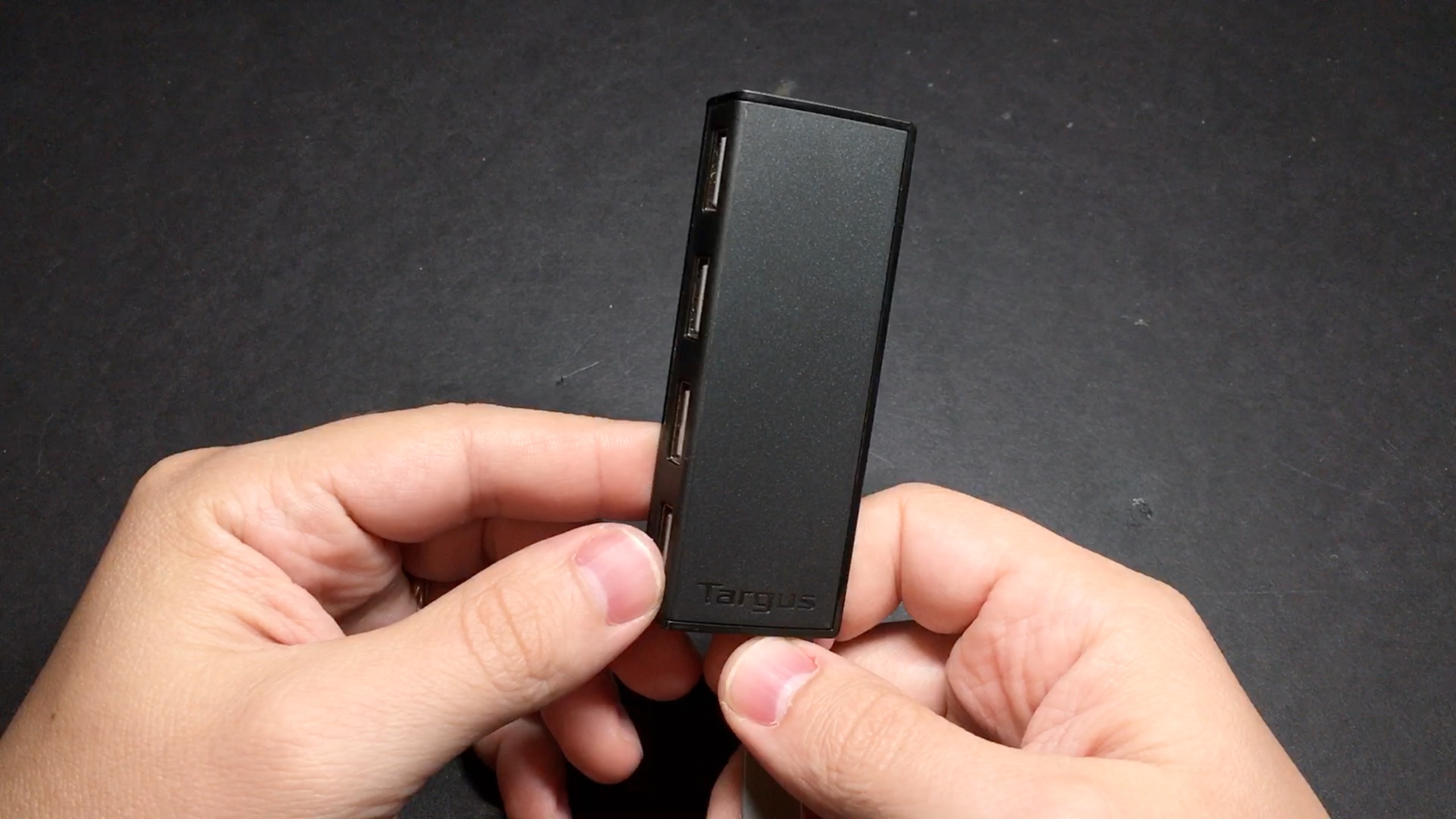
Here’s what mine looked like on the inside:
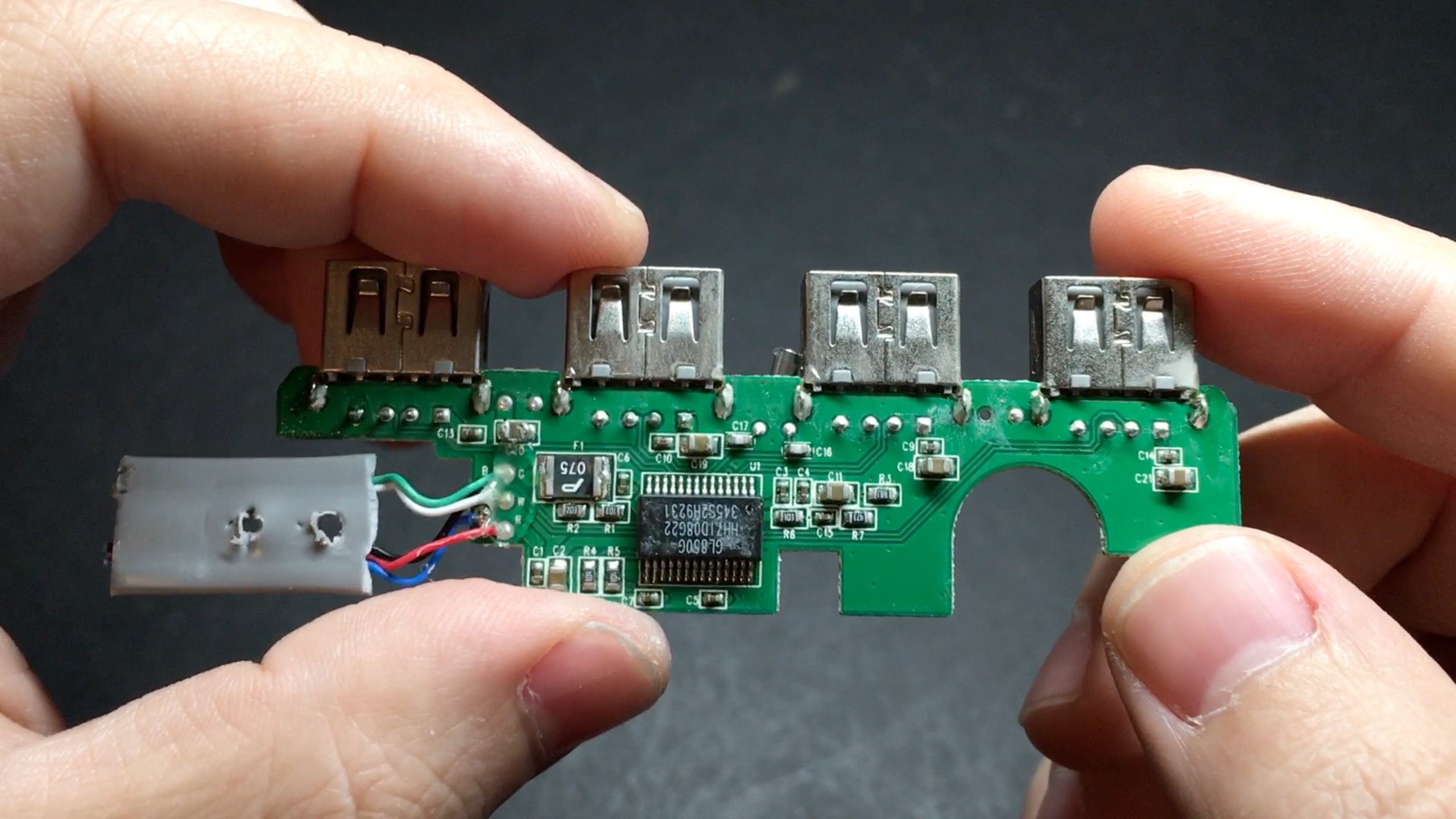
The board itself is tiny – the ports themselves take up most of the space. On mine, I cut off the rightmost port to make it smaller. Then I desoldered two of the other ports for connecting to the Teensy and external USB port. The last one I left alone for having internal Wifi or Bluetooth or whatever.
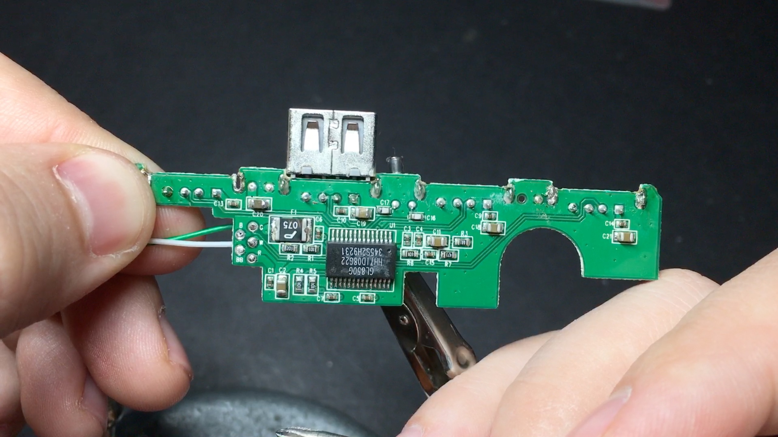
Fair warning: removing the ports is a pain. Watch the video for how I managed to get them off (solder sucker + wick didn’t work well for me in this case).
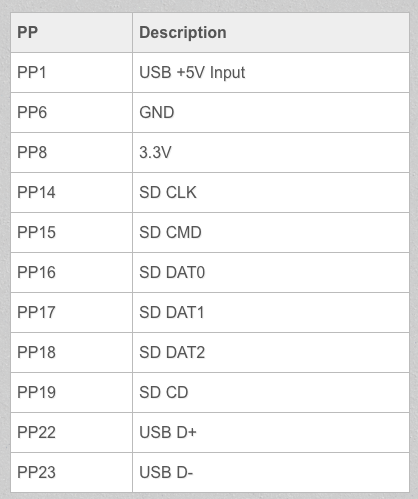
You should go ahead and test it to make sure it still works after removing those ports. You can connect the green/white wires to pads 22/23 (respectively) on the back of the pi, and the red/black wires to pads 1 and 6.
I I just connected a keyboard to each port to make sure it still worked:

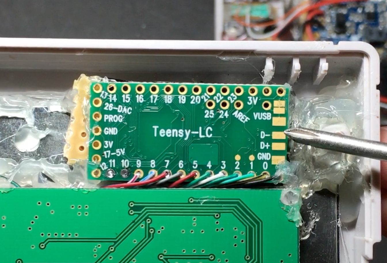
Testing out your controls here is also a good idea. Just connect the Teensy to one of the USB ports on the hub and make sure it still works fine. The pad labeled VUSB is 5v, D- is the white wire, D+ is the green wire and GND is ground.
Now is a good time to go ahead and mount the Pi. We’ll put it right behind (if you’re looking at it from the front of the device) the screen’s controller board. Make sure to lay down something like electrical tape under it. We’ll orient it so that the HDMI port is lined up with where the contrast wheel was:

Put a couple small dabs of glue behind it just to hold it in place. When you’re sure it’s lined up properly, reinforce that with a nice line of glue behind it. It will be sandwiched between the cartridge reader and the display controller board, so the glue is really just to keep it from sliding back when you plug in an HDMI cable.

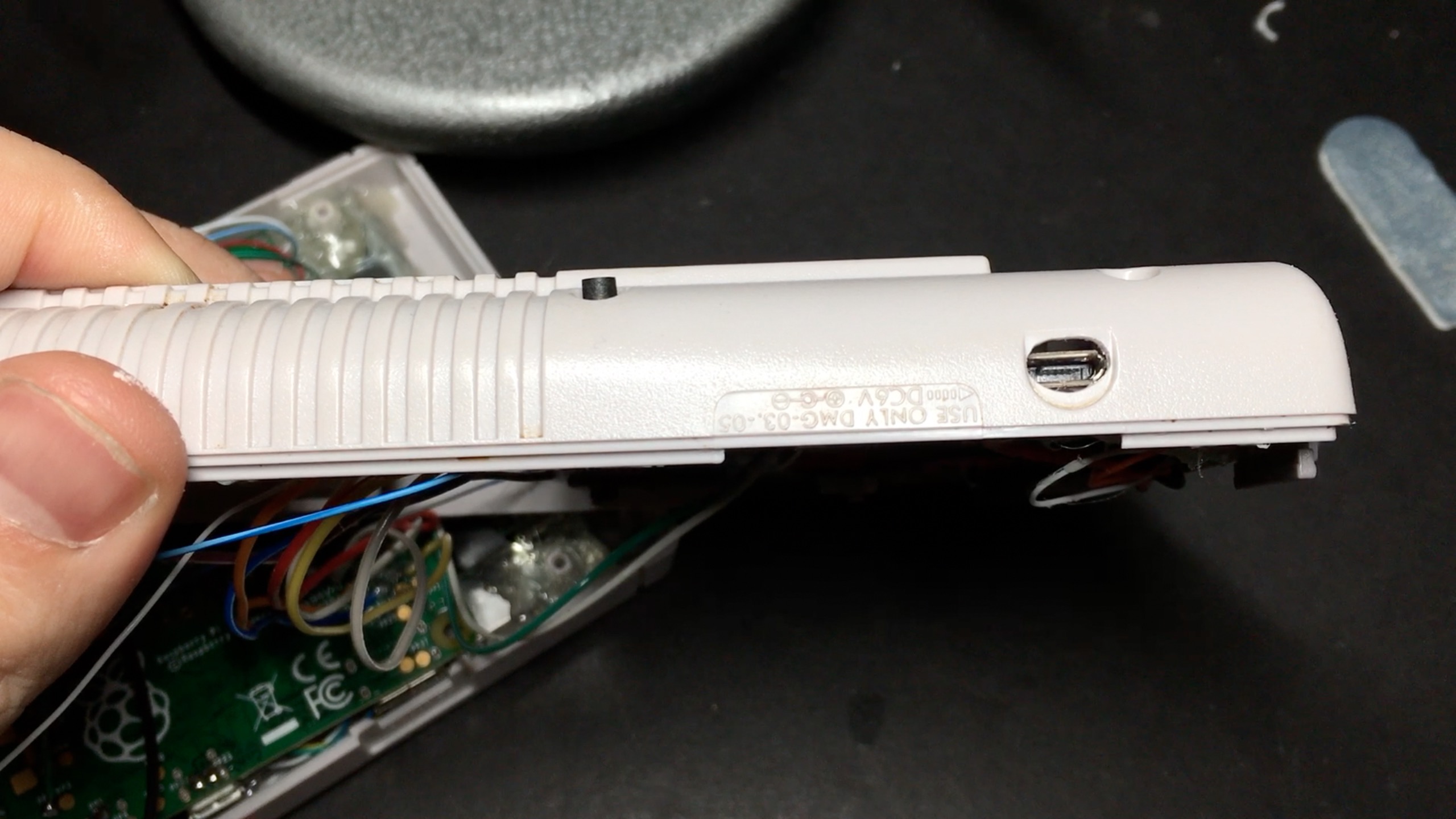
One thing I forgot about when modifying the case is that we need to remove this lip in order for all of the hdmi port to be reachable:

After trimming it down:
For the cartridge reader, you’ll probably need to trim a couple things down.

The pegs that were holding it in place on the motherboard are no longer needed and keep us from closing the case, so cut those off. Then shave down the lip of both screw holes so it’s flush with the rest of it, and put it in place in the back of the case (the video might make this a little clearer):
We’re actually going to forego the screw on the left side, otherwise it will press into the Pi and keep us from closing the case. There are a couple of gray pegs holding it in place for when you insert/remove cartridges though, so we’ll just put a dab of glue to hold that side in place so it doesn’t lift out as we open/close the case.
At this point it’s a good idea to put the two halves of the case together to make sure everything lines up, so you can make any necessary adjustments.
Now for the USB hub. Wire the power pins up to the power strip, connect the Teensy and external USB port (only the data pins for that one, since it is connected directly to the Powerboost for its power). Keep your wires as short as possible to save yourself some space.
I positioned it like so:

You’ll of course want to cover the bottom (as well as the part that will be under the Pi) in electrical tape or something similar.
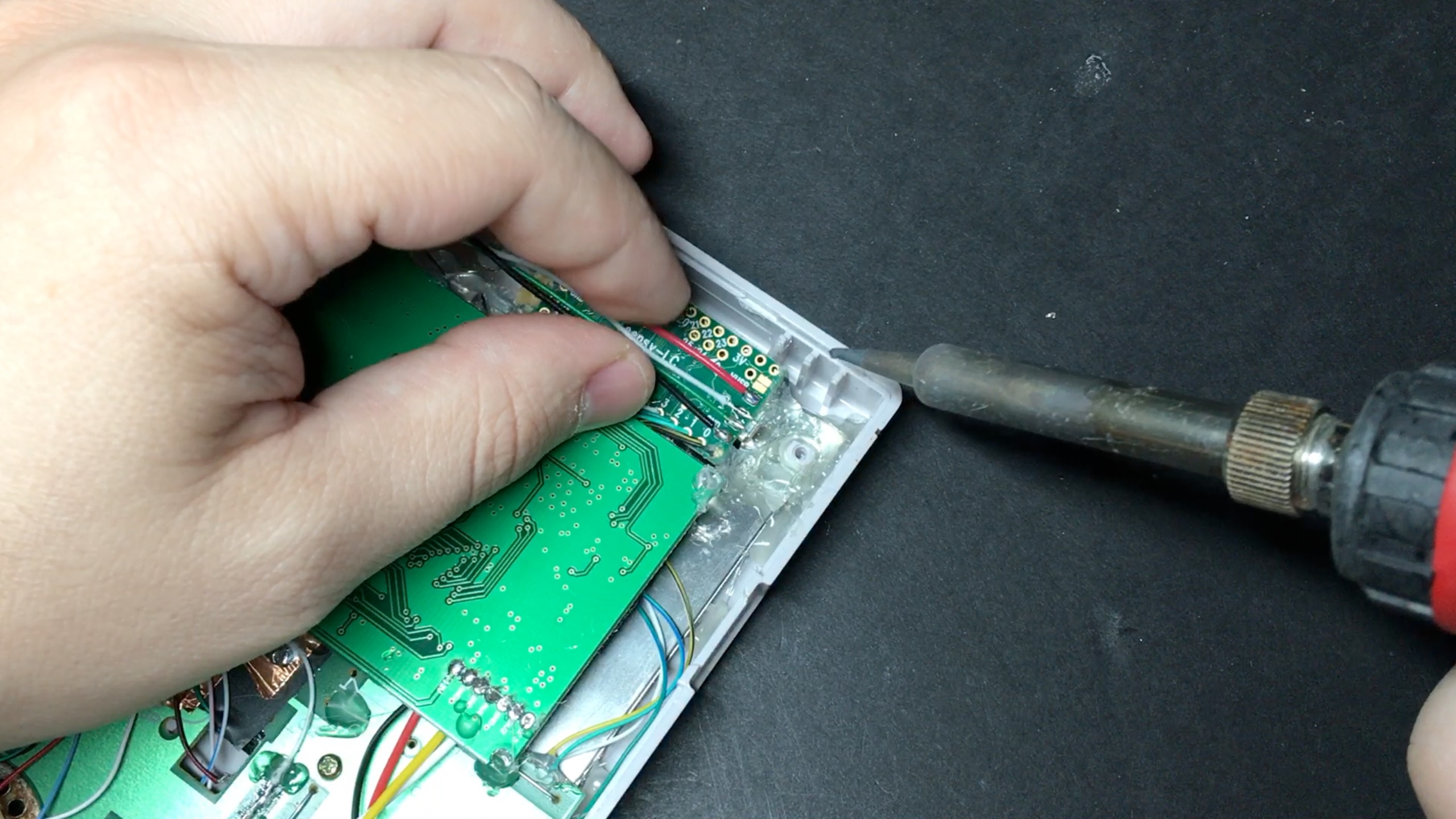
Now it’s time to wire up our audio components. I used a 10kOhm volume wheel potentiometer from Radio Shack. You can attempt to use the one from the old Game Boy, but I’ve found those are typically in pretty rough shape: they can have lots of dead spots, and add static/popping as you adjust the volume. So, even though it’s not a perfect fit, I prefer to just use a new one.

The pins are arranged like so (image taken from Instructables):
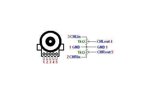
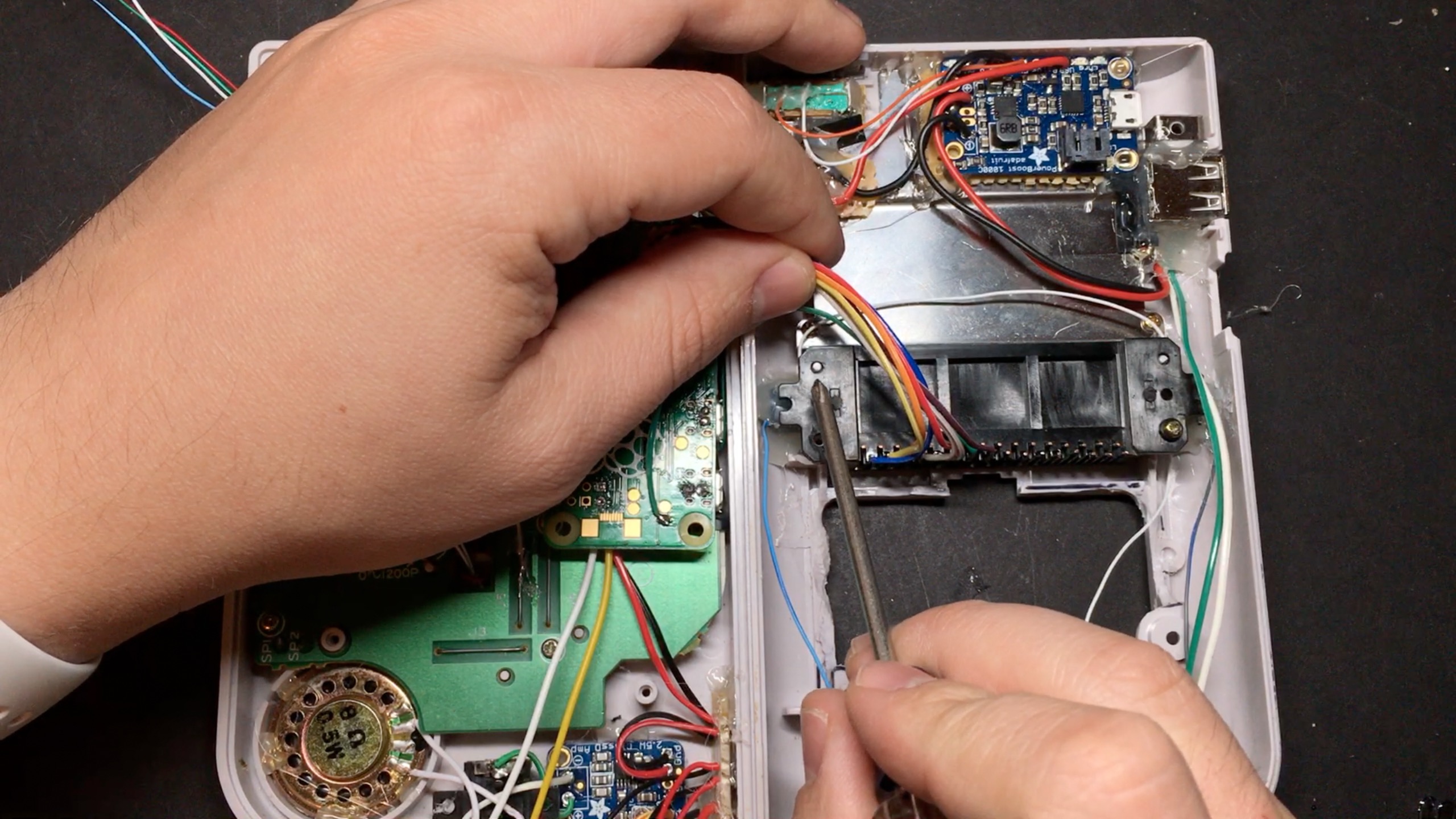
I only did mono sound for my speaker and headphone jack, so all I needed was ground, one input and the corresponding output. The output will go to the A+ pin on your amplifier. The input will come from the output of the audio filter board we made before (check out part 5 for details on that). GPIO pin 18 and ground will be hooked up to the filter.

When you mount your filter, make sure it lines up with the empty space on the opposite side of the case (the bare metal part in the image above). Also make sure you trim any sharp bits on the bottom of it and put some tape or something under it.
The volume wheel will be positioned just like you see below. It needs some support below it though; a piece of perfboard is just the right height.

Now, try closing it up again! There is basically no room in there, so it can be tough to arrange wires properly so that it closes completely. Be prepared for some frustration at this part. 🙂 If you’re having a hard time getting it to close, go back and look at your wiring. Make sure it’s all nice and clean, as flat as you can get it, and that your wires are only as long as they need to be:

Once you get it closed (without the battery at this point) then plug it in and power it on to test it out. If that checks out, connect the battery and close it back up, this time for good!

If all went well, pop in your cartridge, fire it up and play some Donkey Kong. 😀
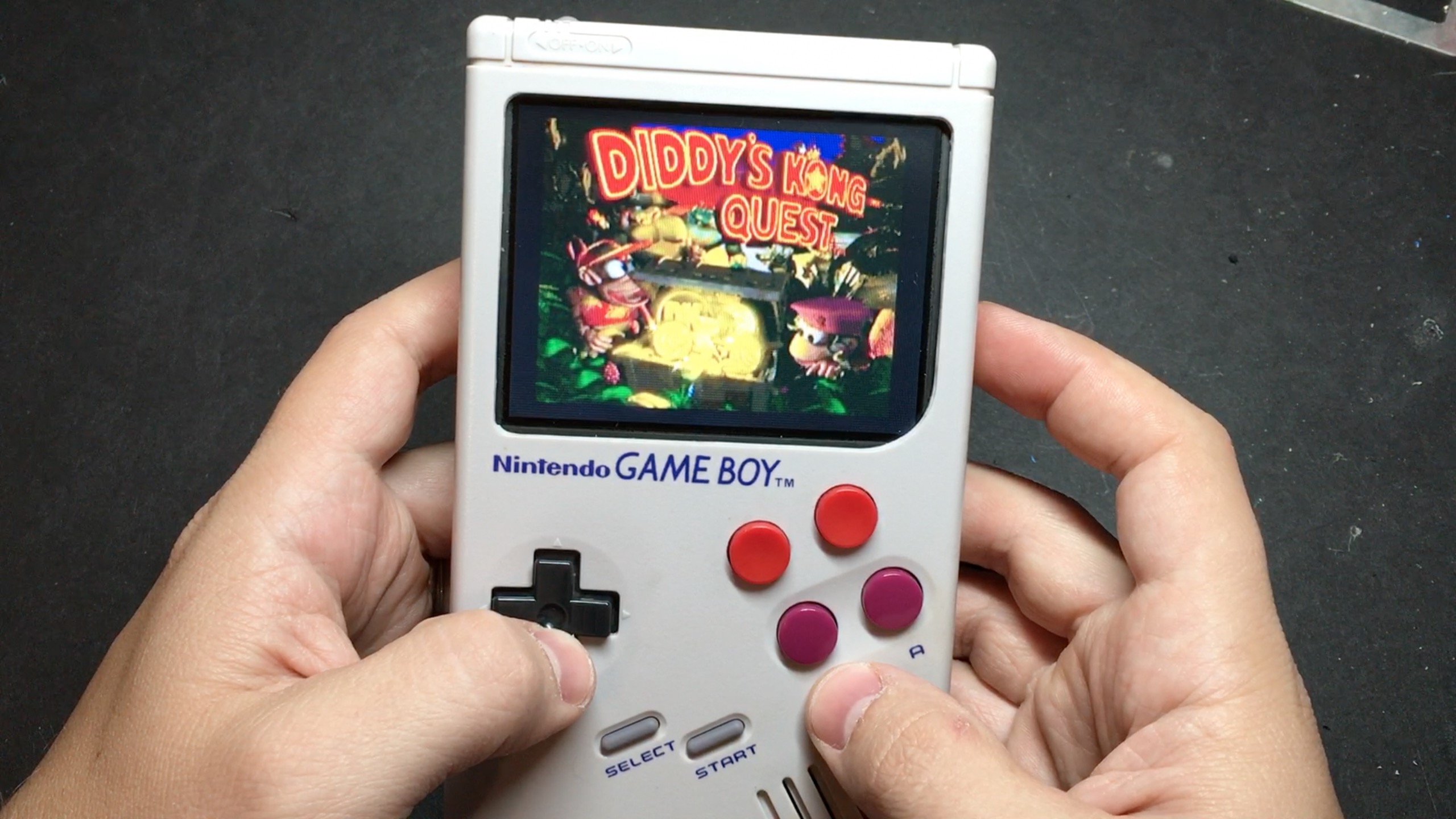
And that’s it!
This took way longer than I had hoped it would, but there you have it, start to finish: how to make a Game Boy Zero.
As for the winner of this one….
It goes to… Matthew from California! I actually already contacted him to make sure he’s in the US and eligible and all that stuff, so it’s not really a surprise for him. But oh well. Congrats again, Matthew! I’ll be testing this out over the next few days to make sure it’s solid, and then I’ll send it off.
Keep an eye out for more projects soon, and if you’ve got an idea for a project, let me know in the comments below!
Until next time!