Page 3 of 4
Re: [Guide] Audio-/Headphone Jack Information Thread
Posted: Tue Aug 09, 2016 4:45 am
by alien0matic
Fleder wrote:alien0matic wrote:
Right out (pin 4) is always "supplied" with audio, but if there are no headphones connected, no one cares.
This is where I think you are wrong. I bet, if you remove the cable going to right out, your speaker wont work anymore.
Re: [Guide] Audio-/Headphone Jack Information Thread
Posted: Tue Aug 09, 2016 4:47 pm
by RetroGamingNow
Radioshack Headphone Jack Diagram can be found here in the guides section
http://www.sudomod.com/forum/viewtopic.php?f=22&t=1209
Re: [Guide] Audio-/Headphone Jack Information Thread
Posted: Mon Aug 15, 2016 8:57 pm
by BigEternalEnd
Hi,
I've been lurking in these forums for a while as I build my gameboy zero. I'm getting ready to work on sound. My DMG headphone jack seems to behave as alien0matic describes it. Perhaps there are indeed two different versions of the DMG jack. There are subtle differences between the tops (non-pin side) of the jacks in the first post and mine. Namely, there is no "3-1" imprint and there are two smaller windows exposing metal on the side opposite of the jack, instead of one bigger window. I have two gameboys, and both the headphone jacks look like this.
See the photo.
Re: [Guide] Audio-/Headphone Jack Information Thread
Posted: Wed Aug 24, 2016 6:29 am
by Fleder
BigEternalEnd wrote:Hi,
I've been lurking in these forums for a while as I build my gameboy zero. I'm getting ready to work on sound. My DMG headphone jack seems to behave as alien0matic describes it. Perhaps there are indeed two different versions of the DMG jack. There are subtle differences between the tops (non-pin side) of the jacks in the first post and mine. Namely, there is no "3-1" imprint and there are two smaller windows exposing metal on the side opposite of the jack, instead of one bigger window. I have two gameboys, and both the headphone jacks look like this.
See the photo.
This looks like a 4 pin jack, as far as i can tell by that blurry picture.
Re: [Guide] Audio-/Headphone Jack Information Thread
Posted: Fri Sep 09, 2016 6:59 am
by Mischief
After having issues with bad audio from my GBZ I thought I would look into if I was wiring the headphone jack wrong. I am now having the same issues with the DMG audio jack as above, I have the wires from the amp to Left out from the amp = pin 2, Right out from the amp = pin 5 Ground from amp = pin 1 and I get audio from my headphones (without any more audio issues YAY!), But then I hooked the speaker positive to pin 3 and ground from speaker to pin 1 and I get no sound from the speaker no matter if I have headphones plugged in or not.
Any help would be appreciated.
Cheers
John
Re: [Guide] Audio-/Headphone Jack Information Thread
Posted: Fri Sep 09, 2016 7:03 am
by valfar
Hi guys
I ordered before I found this guide these audio jack socket:
 http://www.ebay.co.uk/itm/182134092359? ... EBIDX%3AIT
Can you please advise me as to involve this type?
Re: [Guide] Audio-/Headphone Jack Information Thread
Posted: Sat Sep 10, 2016 5:55 pm
by Perifferal
My best guess would be to use a multimeter and just see which ones connect (both with headphones plugged and without). You can then just draw your own diagram. It's a shame the retailer did not include it on the page. It might also be that there is no 'switch' value (LR out might be connected to ground as such), which would mean that you can't use it to switch between speaker and mic.
Re: [Guide] Audio-/Headphone Jack Information Thread
Posted: Sat Sep 10, 2016 8:34 pm
by zerogeek
BigEternalEnd wrote:Hi,
I've been lurking in these forums for a while as I build my gameboy zero. I'm getting ready to work on sound. My DMG headphone jack seems to behave as alien0matic describes it. Perhaps there are indeed two different versions of the DMG jack. There are subtle differences between the tops (non-pin side) of the jacks in the first post and mine. Namely, there is no "3-1" imprint and there are two smaller windows exposing metal on the side opposite of the jack, instead of one bigger window. I have two gameboys, and both the headphone jacks look like this.
See the photo.
I have the same DMG jack (actually 2) as BigEternalEnd - no "3-1" on the top side. If you flip it over with pins up and jack facing you (these are desoldered from the board) and use the numbering scheme from the diagram on p1 of this thread you get the following with a DMM:
NOTHING PLUGGED IN
Pins 3 & 4 have continuity, nothing else
JACK PLUGGED IN
Pin 1 = Sleeve (Ground)
Pin 5 = Ring (Right)
Pin 2 = Tip (Left)
I'm not sure, but based on these findings, I don't understand how this jack will pass audio to the speaker with nothing plugged in. However, it DOES appear that the 1, 2, 5 pinout for using headphones would be right.
I would be VERY excited for anyone to correct me. If not, I'll make a stop at Radio Shack in the morning and pick up Catalog #2740246.
THANKS IN ADVANCE!
Re: [Guide] Audio-/Headphone Jack Information Thread
Posted: Sat Nov 19, 2016 4:49 am
by Oxodao
Insane

If you want to save space for some reason you can use Nexus 5's headphone jack, they are tiny though I don't think they can differenciate when the speaker is plugged or not...
http://www.ebay.com/itm/BRAND-NEW-HEADP ... Sw7hRWQvxr
Re: [Guide] Audio-/Headphone Jack Information Thread
Posted: Sun Dec 04, 2016 10:44 am
by larsen2011
alien0matic wrote:I did use a DMM, I inserted a headphone into the jack and I measured continuity on all pins. There are NO output pins.
The pins you labeled with 1, 2 and 5 are correct to be ground, left in and right in. But there is NO continuity betweent pin 3 and pins 1,2 or 5. Same goes for pin 4.
But there IS a connection between 3 and 4. The connection is cut when the headphone is inserted.
Have a look into this thread:
http://www.sudomod.com/forum/viewtopic.php?f=22&t=197
He connected the input pins (2 and 5) to pin 4 and pin 3 to the speaker. I did something similar, I have stereo sound connected to the jack and forward right to Pin 3.
I only have this image, everything else is blurry. Green is left, yellow is right, black is ground. White goes to the speaker. The jack is in the same orientation as in your image. This way everything works as expected.
[spoiler="wiring image"]IMG_20160807_130332.jpg[/spoiler]
I second that. After wiring per the general wiring diagram and per the shown wiring for the original GB jack, I had no sound. After checking the resistance on my jack and reading through this thread, I found my jack to also be different to the one shown in the first thread. The wiring from @alien0matic works perfectly.
@Fleder here are some pictures of my jack, which are not as blurry as the ones yet in here, in case you want to update the first post, showing that there might be different wiring solutions.
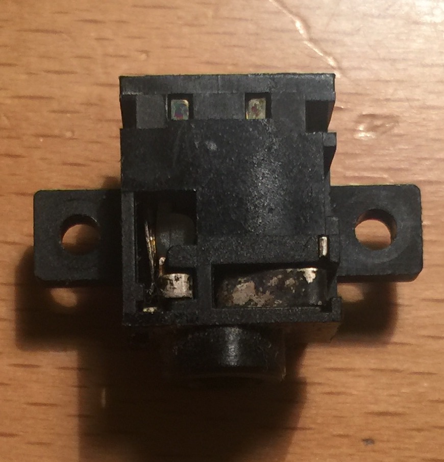
- IMG_7507.JPG (144.66 KiB) Viewed 14292 times
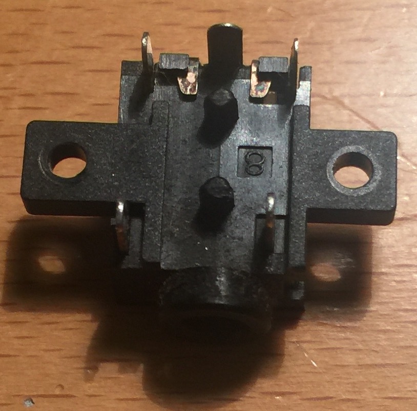
- IMG_7508.JPG (142.38 KiB) Viewed 14292 times