Page 1 of 4
Wiring Diagram: mintyPi controller PCB
Posted: Sat Jun 24, 2017 12:04 pm
by djbriane
Here is the final wiring diagram based on Wermy's guide for anyone who wants a full picture of what connects to what. One thing to note is the Raspberry Pi actually sits ABOVE the controller PCB, but for some reason Fritzing doesn't allow me order the components in that way (if anyone knows why, please PM me!).
mintyPi Controller PCB Wiring Diagram
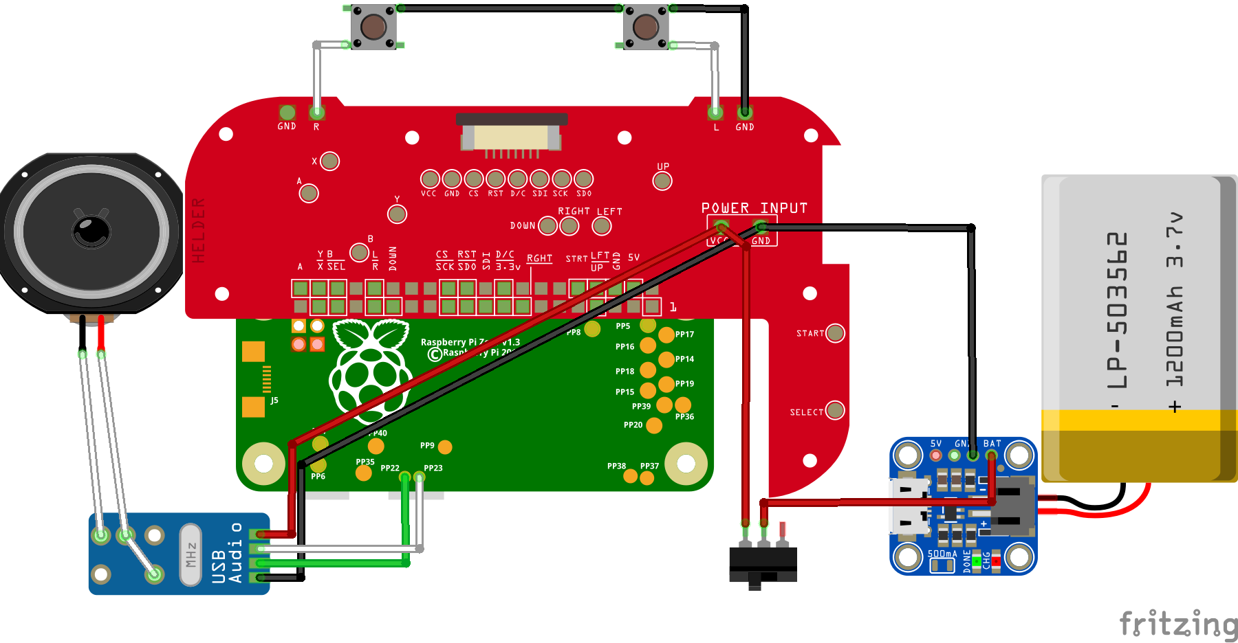
- mintypi-wiring-v1-final_bb.png (229.97 KiB) Viewed 12134 times
Re: [WIP] Wiring Diagram: mintyPi controller PCB
Posted: Tue Jul 18, 2017 9:14 am
by wermy
Thanks again for doing this.

The only things I'd tweak are powering the USB sound card from the button PCB (connected to the same power input pads). The way you have it will work, but you need less wires to reach the button PCB pads. I also found that the resistors weren't really necessary.
Re: [WIP] Wiring Diagram: mintyPi controller PCB
Posted: Tue Jul 18, 2017 10:53 am
by djbriane
wermy wrote: ↑Tue Jul 18, 2017 9:14 am
Thanks again for doing this.
The only things I'd tweak are powering the USB sound card from the button PCB (connected to the same power input pads). The way you have it will work, but you need less wires to reach the button PCB pads. I also found that the resistors weren't really necessary.
Updated the diagram to match your guide - let me know if anything looks incorrect!
Re: Wiring Diagram: mintyPi controller PCB
Posted: Wed Jul 19, 2017 8:28 am
by Kyran
I can't seem to upload a pic from my phone, but anyways, is there a reason my pi won't boot/power up? The screen is receiving power through the pcb but not the pi and I'm not sure why, I've got everything soldered as depicted above and it even works when I powered the board during the testing stage of wermys guide but after putting the rest together(twice now) my screen is the only thing that gets power(Not white, it's a black screen but can see the back light come on)
Re: Wiring Diagram: mintyPi controller PCB
Posted: Wed Jul 19, 2017 1:30 pm
by Helder
Upload pictures to a website like postimg.org and then post the links here to the images. Also this has what to do with the wiring diagram? You need to stick to your thread or make a new one with your problems instead of posting this everywhere. It's likely a bridge or a broken solder connection from the Pi to the PCB, are you testing continuity like Wermy did in the video to each test pad?
Re: Wiring Diagram: mintyPi controller PCB
Posted: Wed Jul 19, 2017 9:56 pm
by dryja123
I think the wiring for the R button is wrong. You have the wire going from the button to the R pad but the leg That you are connected to is also sharing the common ground with L.
Re: Wiring Diagram: mintyPi controller PCB
Posted: Thu Jul 20, 2017 6:09 am
by HoolyHoo
dryja123 wrote: ↑Wed Jul 19, 2017 9:56 pm
I think the wiring for the R button is wrong. You have the wire going from the button to the R pad but the leg That you are connected to is also sharing the common ground with L.
This is true.
R pad wire should be connected to one of those two bottom pins on that switch.
Re: Wiring Diagram: mintyPi controller PCB
Posted: Thu Jul 20, 2017 9:08 am
by djbriane
dryja123 wrote: ↑Wed Jul 19, 2017 9:56 pm
I think the wiring for the R button is wrong. You have the wire going from the button to the R pad but the leg That you are connected to is also sharing the common ground with L.
Good catch! Fixed it and attached an updated image/fritzing file.
Thanks!
Re: Wiring Diagram: mintyPi controller PCB
Posted: Thu Jul 20, 2017 9:09 am
by wermy
Hah, I happened to load the page after you fixed it but just before you replied, @djbriane. I was sitting here looking at the diagram going "that looks right to me... What are they talking about?"
Nice catch guys.
Re: Wiring Diagram: mintyPi controller PCB
Posted: Tue Jul 25, 2017 9:25 am
by Lphillimore
While most are obvious, what does Pad1 connect to?