Page 1 of 2
help troubleshooting my wiring setup
Posted: Sat Sep 16, 2017 8:27 pm
by orionpax
I have everything wired like so:
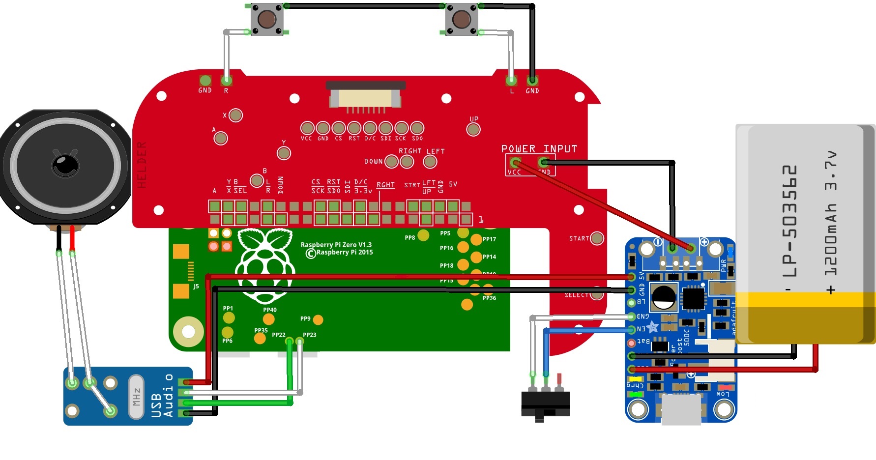
- mypi wiring.jpg (290.39 KiB) Viewed 8694 times
Everything works fine when I power the R Pi directly, but when i power it on via switch & battery the screen flickers as if it isn't getting enough power to come on fully.
Re: help troubleshooting my wiring setup
Posted: Sat Sep 16, 2017 8:33 pm
by dryja123
Re: help troubleshooting my wiring setup
Posted: Sat Sep 16, 2017 10:33 pm
by orionpax
I checked for continuity and the soldered points were fine. I am only ready ~2.5v no matter how long I wait for a full charge.
Re: help troubleshooting my wiring setup
Posted: Sun Sep 17, 2017 4:27 am
by dryja123
Are you getting 2.5v at both the PCB and the Pi? Also, are you using the battery monitor? What battery charger are you using and do you ever get a green light saying the battery is charged?
Can you post pictures?
Re: help troubleshooting my wiring setup
Posted: Sun Sep 17, 2017 2:43 pm
by orionpax
dryja123 wrote: ↑Sun Sep 17, 2017 4:27 am
Are you getting 2.5v at both the PCB and the Pi? Also, are you using the battery monitor? What battery charger are you using and do you ever get a green light saying the battery is charged?
Can you post pictures?
I am getting 2.5v at the PCB and the Pi. I don't hav ethe battery monitor. I'm using the powerboost 500 charger
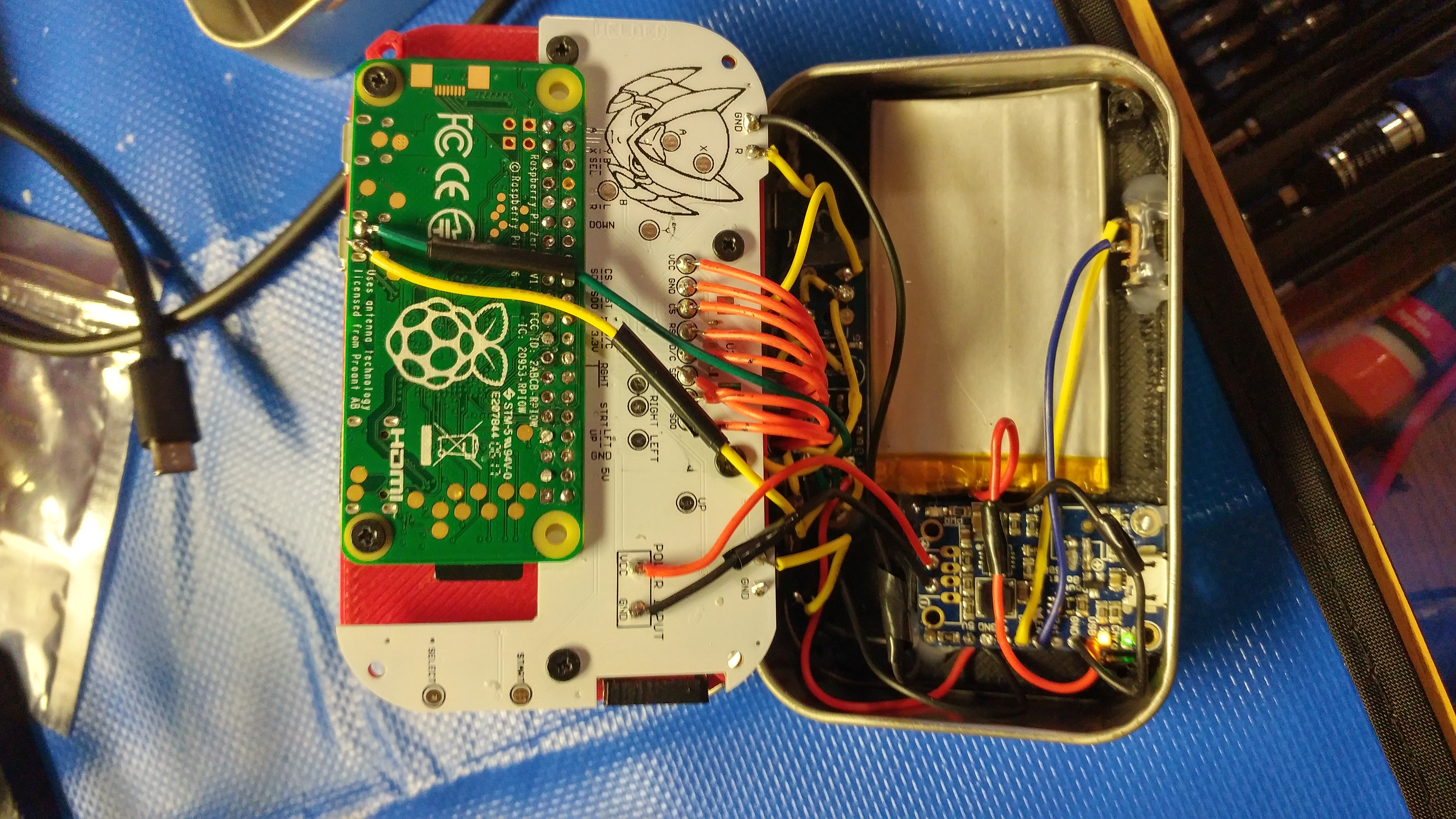
- 20170917_133747_HDR.jpg (6.96 MiB) Viewed 8662 times
Re: help troubleshooting my wiring setup
Posted: Sun Sep 17, 2017 2:53 pm
by dryja123
orionpax wrote: ↑Sun Sep 17, 2017 2:43 pm
I am getting 2.5v at the PCB and the Pi. I don't hav ethe battery monitor. I'm using the powerboost 500 charger
Did you solder those battery wires together before you wrapped them in electrical tape?
Give me your voltage reading on the 500. If it's low at these points you have an issue with your battery or charging board. I would look at those battery wires.
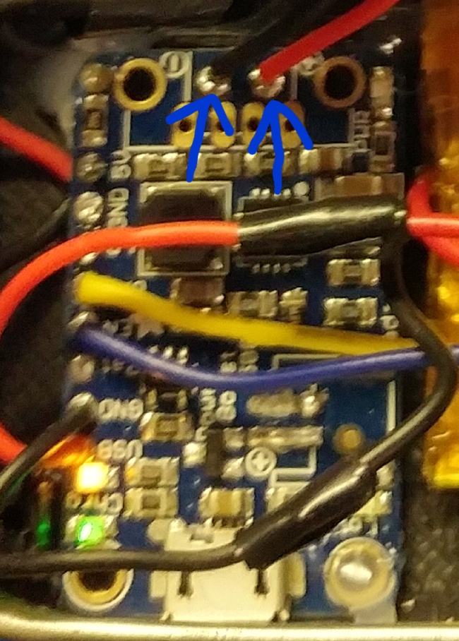
- 20170917_164923.jpg (435.81 KiB) Viewed 8661 times
Re: help troubleshooting my wiring setup
Posted: Sun Sep 17, 2017 2:59 pm
by orionpax
dryja123 wrote: ↑Sun Sep 17, 2017 2:53 pm
orionpax wrote: ↑Sun Sep 17, 2017 2:43 pm
I am getting 2.5v at the PCB and the Pi. I don't hav ethe battery monitor. I'm using the powerboost 500 charger
Did you solder those battery wires together before you wrapped them in electrical tape?
Give me your voltage reading on the 500. If it's low at these points you have an issue with your battery or charging board. I would look at those battery wires.
I did solder them. I'm only getting 2.4v at those test points
Re: help troubleshooting my wiring setup
Posted: Sun Sep 17, 2017 5:10 pm
by dryja123
orionpax wrote: ↑Sun Sep 17, 2017 2:59 pm
I did solder them. I'm only getting 2.4v at those test points
Cool, try this now. Take off the electrical tape and test your voltage on your battery wires. If you get 2.4v your battery is flat.
Also, solder the battery wires to the + and - where the JST connector was. This is similar to how you're supposed to solder the battery to the micro lipo charger. I'm thinking the battery isn't getting charged where it was at.
I'm making this assumption based on the wiring config for the GBZ using the 1000c in this wiring diagram. This is how I wired mine and had no battery / charging issues.
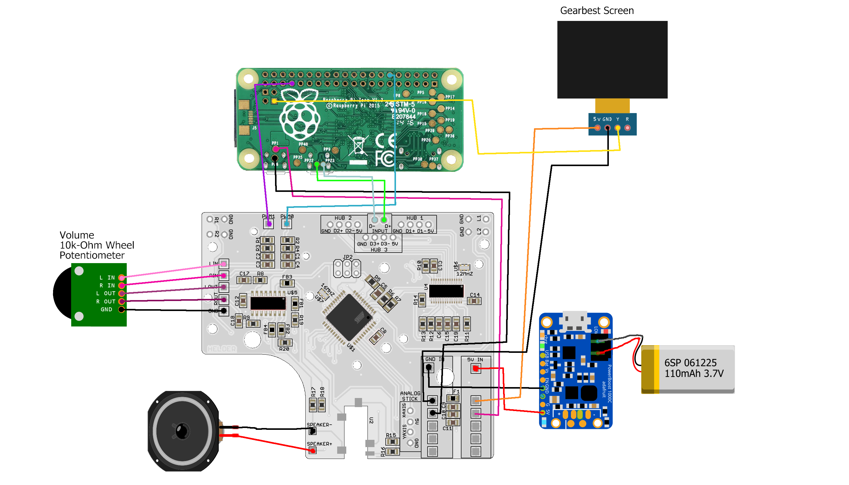
- AIO_2.2_Wiring-1.png (736.76 KiB) Viewed 8647 times
Re: help troubleshooting my wiring setup
Posted: Sun Sep 17, 2017 7:42 pm
by orionpax
dryja123 wrote: ↑Sun Sep 17, 2017 5:10 pm
orionpax wrote: ↑Sun Sep 17, 2017 2:59 pm
I did solder them. I'm only getting 2.4v at those test points
Cool, try this now. Take off the electrical tape and test your voltage on your battery wires. If you get 2.4v your battery is flat.
Also, solder the battery wires to the + and - where the JST connector was. This is similar to how you're supposed to solder the battery to the micro lipo charger. I'm thinking the battery isn't getting charged where it was at.
I'm making this assumption based on the wiring config for the GBZ using the 1000c in this wiring diagram. This is how I wired mine and had no battery / charging issues.
I'm getting ~3.4v from the battery. The pads for + and - from the JST connector were torn off.
Re: help troubleshooting my wiring setup
Posted: Mon Sep 18, 2017 7:02 am
by dryja123
The battery is meant to be connected to the JST connector and I'm not sure if you can charge from any of those other spots on the charger board. I would suggest replacing it with a micro lipo or the alternative charger that Wermy said would be compatible in his latest update video.