http://2.bp.blogspot.com/_Aw-oTul-e1Y/T ... wiring.png
Helder v2.2 - what's wrong with my wiring
-
144TECH

- Posts: 325
- Joined: Fri Jan 06, 2017 7:30 am
- Location: Amsterdam
- Has thanked: 256 times
- Been thanked: 71 times
Re: Helder v2.2 - what's wrong with my wiring
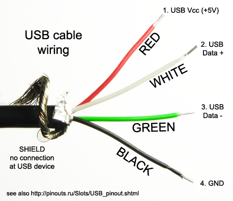
Okay, well let us know what happens when you connect the aio board to the pc.. if you use a old usb cable to solder the wires red and black, remember that white and green are opposite of @helder 's drawing in his drawing he marked Green as D+ and White as D- while official is : Green D- and White D+. (same as the free usb ports) that's the right order. but the two wires from the Button board are reversed. (@Helder should change the drawing to simplify it) Good luck and let us know how it went.  http://s1.hubimg.com/u/8259106_f520.jpg
http://2.bp.blogspot.com/_Aw-oTul-e1Y/T ... wiring.png
http://2.bp.blogspot.com/_Aw-oTul-e1Y/T ... wiring.png
* Very Rare * GBZ 640x480 v3 Stock Looks 6000MAH
http://www.sudomod.com/forum/viewtopic.php?f=43&t=4863
http://www.sudomod.com/forum/viewtopic.php?f=43&t=4863

Re: Helder v2.2 - what's wrong with my wiring
Thanks Tech really appreciate the help!!! Will add the USB over the weekend,144TECH wrote:Okay, well let us know what happens when you connect the aio board to the pc.. if you use a old usb cable to solder the wires red and black, remember that white and green are opposite of @helder 's drawing in his drawing he marked Green as D+ and White as D- while official is : Green D- and White D+. (same as the free usb ports) that's the right order. but the two wires from the Button board are reversed. (@Helder should change the drawing to simplify it) Good luck and let us know how it went.
http://2.bp.blogspot.com/_Aw-oTul-e1Y/T ... wiring.png
BTW - best avatar ever Blanka rules!

Re: Helder v2.2 - what's wrong with my wiring
Helder wrote:Hook up the board to a pc using a usb cable and see if the pc shows the hub and arduino controller.Tron wrote:Ok so I've de soldered everything and resoldered to a new pi zero and still have the same problem.Helder wrote:Twist the usb wires and also be sure PP22 and PP23 are not touching the Ground pad right next to each point. Use a multimeter to be sure the wires aren't grounded.
I found a multimeter I checked the impedance between ground and the two USB pads before soldering, then soldered on the two USB wires and get the same level of impedance so I'm not making a connection to ground.
I've also twisted the wires as tight as possible.
After all of the above I still have the same problem.
Is it possible that there is something up with the AIO board?
Hi Helder
I tried this and wired the way tech advised above and also the other way following your wiring diagram colours to be sure. No luck I'm afraid it doesn't register on a PC unfortunately.
Anything else that's possible?
Thanks for your help Helder
-
144TECH
- Posts: 325
- Joined: Fri Jan 06, 2017 7:30 am
- Location: Amsterdam
- Has thanked: 256 times
- Been thanked: 71 times
Re: Helder v2.2 - what's wrong with my wiring
I Think i know what the culprit is  but let's wait what Helder is gonna say
Maybe you can make a picture on how you wired it and hooked it up to the pc..
Question is, you didn't get any response from the pc ? or any error message or something? or just nothing?
Don't forget to remove the powerboost and all that stuff, just wire like here below, the pc usb provides enough power!
http://imgur.com/a/QDU0f
And after that.. you should.... end up like this
http://share.pho.to/Ab937
And , with the drawing of helder, i meant white and green are opposite compared to the 3 usb ports next to it so my bad lol
Shoooo Riu Ken
Last edited by 144TECH on Sat Jan 28, 2017 9:56 am, edited 1 time in total.
* Very Rare * GBZ 640x480 v3 Stock Looks 6000MAH
http://www.sudomod.com/forum/viewtopic.php?f=43&t=4863
http://www.sudomod.com/forum/viewtopic.php?f=43&t=4863
-
Helder

- Trailblazer

- Posts: 2985
- Joined: Thu May 05, 2016 8:33 am
- Location: Rogers, AR
- Has thanked: 1459 times
- Been thanked: 3114 times
Re: Helder v2.2 - what's wrong with my wiring
IT should show up as a usb hub and the Atmega32u4 or Arduino like it shows in 144TECH's second photo. If it doesn't do atleast the hub you might just need to reflow the solder of the usb hub chip and the 12mhz resonator.Tron wrote:
Hi Helder
I tried this and wired the way tech advised above and also the other way following your wiring diagram colours to be sure. No luck I'm afraid it doesn't register on a PC unfortunately.
Anything else that's possible?
Thanks for your help Helder
Chat with me and other members On Discord
Don't contact me about obtaining my board files (as you will not get them). If my Boards or PCB Kits are sold out, they will be restocked as soon as I can get them and there is demand for them. You can join the mailing list on my Website to be notified when they are available.
Helder's Game Tech Website
We will not support any cloned work so don't come to us with technical issues to resolve, go talk to the cloner for help.
Re: Helder v2.2 - what's wrong with my wiring
Thanks Helder,Helder wrote:IT should show up as a usb hub and the Atmega32u4 or Arduino like it shows in 144TECH's second photo. If it doesn't do atleast the hub you might just need to reflow the solder of the usb hub chip and the 12mhz resonator.Tron wrote:
Hi Helder
I tried this and wired the way tech advised above and also the other way following your wiring diagram colours to be sure. No luck I'm afraid it doesn't register on a PC unfortunately.
Anything else that's possible?
Thanks for your help Helder
It's wired exactly as TECH's picture, the PC is picking up that there is a USB connected by says it has malfunctioned and can not be recognised.
I have no idea about soldering chips, that is way way beyond me sorry.
-
144TECH
- Posts: 325
- Joined: Fri Jan 06, 2017 7:30 am
- Location: Amsterdam
- Has thanked: 256 times
- Been thanked: 71 times
Re: Helder v2.2 - what's wrong with my wiring
Don't worry it will be allright 
 one last try is change white and green, just in case...
After that it's gonna be soldering time ...
After that it's gonna be soldering time ...
* Very Rare * GBZ 640x480 v3 Stock Looks 6000MAH
http://www.sudomod.com/forum/viewtopic.php?f=43&t=4863
http://www.sudomod.com/forum/viewtopic.php?f=43&t=4863
-
rg247junocom
- Posts: 5
- Joined: Sun Jan 01, 2017 6:43 pm
- Location: GB
- Has thanked: 3 times
- Contact:
Re: Helder v2.2 - what's wrong with my wiring
This is my first input on your board. I had the same problem with the controls not responding. And sure enough, the PP23 wire was touching the connection next to it. I had to clean the space between the two connections very well because the solder has run over to ground the PP23. Thanks a lot for the tip. I was able to set up my Gameboy Zero without any problems. My only complain is that the writing is so small on the screen I had to use a jeweler's magnifier to be able to read it. Again, thank you for the tip. 
Another problem that I have now regarding wiring is that I'd like to set up a micro USB port by which I can power up the Gameboy Zero and charge the battery just like tho one that comes with the powerboost 1000c. Any suggestions will help.
Another problem that I have now regarding wiring is that I'd like to set up a micro USB port by which I can power up the Gameboy Zero and charge the battery just like tho one that comes with the powerboost 1000c. Any suggestions will help.
-
blameblaine
- Posts: 39
- Joined: Fri Jul 22, 2016 12:31 pm
- Has thanked: 1 time
- Been thanked: 9 times
Re: Helder v2.2 - what's wrong with my wiring
How can I adjust the USB speed settings? Will that help with response if the pad presses?144TECH wrote:Wow, the green wire seems to touch the Ground, the hole next to it.
you should remove the wires, and strip them, then tin them, and snip them off nice and short, now theres to much unisolated wire sticking out, this can cause them to touch each other.
If it doesnt work thereafter, you need to adjust with usb speed settings.
When you re-solder the wires, just tip the pads until they melt, and then shove the wire in the melted tinpad, this prevents the isolation of the wire beeing pulled back due the heat.
You should get it more like this:and take caution that there is a space between the yellow lines.
good Luck
-
Helder
- Trailblazer
- Posts: 2985
- Joined: Thu May 05, 2016 8:33 am
- Location: Rogers, AR
- Has thanked: 1459 times
- Been thanked: 3114 times
Re: Helder v2.2 - what's wrong with my wiring
Go to my support thread for the speed fix and try retropie v4.02.
Chat with me and other members On Discord
Don't contact me about obtaining my board files (as you will not get them). If my Boards or PCB Kits are sold out, they will be restocked as soon as I can get them and there is demand for them. You can join the mailing list on my Website to be notified when they are available.
Helder's Game Tech Website
We will not support any cloned work so don't come to us with technical issues to resolve, go talk to the cloner for help.
Don't contact me about obtaining my board files (as you will not get them). If my Boards or PCB Kits are sold out, they will be restocked as soon as I can get them and there is demand for them. You can join the mailing list on my Website to be notified when they are available.
Helder's Game Tech Website
We will not support any cloned work so don't come to us with technical issues to resolve, go talk to the cloner for help.
Who is online
Users browsing this forum: No registered users and 1 guest