
unrelated to your actual question but still:
Do not wire your second Video Input to the Ground Pin on the Pi.
Look here: http://sudomod.com/forum/viewtopic.php?f=22&t=958
power supply


-
RxBrad

- Posts: 278
- Joined: Fri Jul 22, 2016 9:10 am
- Has thanked: 125 times
- Been thanked: 160 times
- Contact:
Re: power supply
Does anyone care to explain this to amateurs like myself? Looks like there are about 4 other people in this thread hoping for an explanation...SidSilver wrote:If you have a SPST or a SPDT, you should put the switch on the battery's red wire.
If you have a DPST or a DPDT, you should put the switch on the battery's red wire and in parallel on the usb-in red wire.
Pictures are nice.


-
SidSilver
- Posts: 263
- Joined: Sun May 22, 2016 6:22 am
- Location: France
- Has thanked: 137 times
- Been thanked: 37 times
-
RxBrad
- Posts: 278
- Joined: Fri Jul 22, 2016 9:10 am
- Has thanked: 125 times
- Been thanked: 160 times
- Contact:
Re: power supply
Thanks... Because it has 4 pins, is it safe to say that the original DMG power switch is DPDT?SidSilver wrote:
If you have a 'dt' you only need to use the middle pin and one of the side pins.
And since this particular power supply doesn't seem to have an engage pin, I'm guessing that we don't want to use the same two pins that the Adafruit PS uses, and instead use the two "on" pins on the DMG switch. (?)
Now, how do you wire the battery and mini USB port to these pins? The only way I can envision involves putting the battery and USB port in the same circuit, and I would think that's bad.
-
SidSilver
- Posts: 263
- Joined: Sun May 22, 2016 6:22 am
- Location: France
- Has thanked: 137 times
- Been thanked: 37 times
Re: power supply
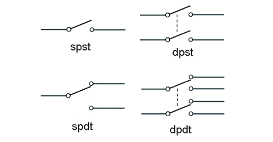
4 pins would be DPST
On my picture, the left pins with the moving part are the center pins of the switch. The other pins are the side pins.
For example here is à SPDT
The center pin is the 'mobile' part of the schema

DPDT is the same but with 2 rows of pin.
The rows are not connected to each other.
On my picture, the left pins with the moving part are the center pins of the switch. The other pins are the side pins.
For example here is à SPDT
The center pin is the 'mobile' part of the schema
DPDT is the same but with 2 rows of pin.
The rows are not connected to each other.
-
RxBrad
- Posts: 278
- Joined: Fri Jul 22, 2016 9:10 am
- Has thanked: 125 times
- Been thanked: 160 times
- Contact:
Re: power supply
Thanks.. Still a bit over my head, but that's okay.
All I know is that when the switch is off, the two blue pins are connected; and when it's on, the two red pins are connected. The blue pins aren't connected to the red pins in any way. At least that's what my bush league multimeter testing tells me.

I still need to figure out how exactly these should be hooked up to the battery and microUSB port.
All I know is that when the switch is off, the two blue pins are connected; and when it's on, the two red pins are connected. The blue pins aren't connected to the red pins in any way. At least that's what my bush league multimeter testing tells me.
I still need to figure out how exactly these should be hooked up to the battery and microUSB port.
-
statikeffeck

- Posts: 31
- Joined: Tue Jul 05, 2016 8:35 pm
- Has thanked: 23 times
- Been thanked: 5 times
Re: power supply
So in that case, It's none of the acronymsRxBrad wrote:Thanks.. Still a bit over my head, but that's okay.
All I know is that when the switch is off, the two blue pins are connected; and when it's on, the two red pins are connected. The blue pins aren't connected to the red pins in any way. At least that's what my bush league multimeter testing tells me.
I still need to figure out how exactly these should be hooked up to the battery and microUSB port.
Sounds to me like the switch is a DPST except with the "moving" parts inverse of each other. In any case, with your power supply you don't have the "switching" enable feature of the AdaFruit... so like another poster said, you can put the switch along the Red + Battery (B+) wire. I found out that the power supply does not function with the battery disconnected even if you have it plugged in... so that would effectively turn the whole thing off.
Here's my idea of how to wire it (please correct me if I'm wrong):

Because you don't want to power anything when it is in the "Off" position, don't connect anything to the "blue" points. Just be careful before shutting off the power, to shut down the pi zero through the menus so you don't corrupt the SD card.
Edit: one downside though, if you shut "off" the switch, everything will be fully off and you will not be able to charge the battery. To remedy this, you can switch "On" the unit, so it starts charging the battery. Then, in the system menus, shutdown the raspberry pi. Leave the switch in the "On" position as it charges. When you are done charging, you can then switch it "off". For safety's sake, make sure you do not leave the unit charging if you're not around!
-
RxBrad
- Posts: 278
- Joined: Fri Jul 22, 2016 9:10 am
- Has thanked: 125 times
- Been thanked: 160 times
- Contact:
Re: power supply
Thanks! That all makes sense.
Bummer that it makes charging seem somewhat inconvenient, however. I think I might have to break down and buy the pricey Adafruit PS, which has the additional benefit of a low battery indicator. I think it would technically be possible to use an external LiPo battery alarm (used by drone hobbyists, it appears) on this alternative PS to hack together a low battery indicator, however.
Bummer that it makes charging seem somewhat inconvenient, however. I think I might have to break down and buy the pricey Adafruit PS, which has the additional benefit of a low battery indicator. I think it would technically be possible to use an external LiPo battery alarm (used by drone hobbyists, it appears) on this alternative PS to hack together a low battery indicator, however.
Who is online
Users browsing this forum: No registered users and 1 guest