While, technically, the BW7 display works without modifications, my experience was that it had very noticeable flickering when used that way. I'd really recommend soldering a jumper wire like so:


So I just snip the current attachment and solder the wire to the board? Also where are the connections on the pi zero? Do you have a image of that. I appreciate you help!RxBrad wrote:@Rog585
While, technically, the BW7 display works without modifications, my experience was that it had very noticeable flickering when used that way. I'd really recommend soldering a jumper wire like so:
Sorry just seen that I solder to the chip I don't need to cut the connection.Rog585 wrote:So I just snip the current attachment and solder the wire to the board? Also where are the connections on the pi zero? Do you have a image of that. I appreciate you help!RxBrad wrote:@Rog585
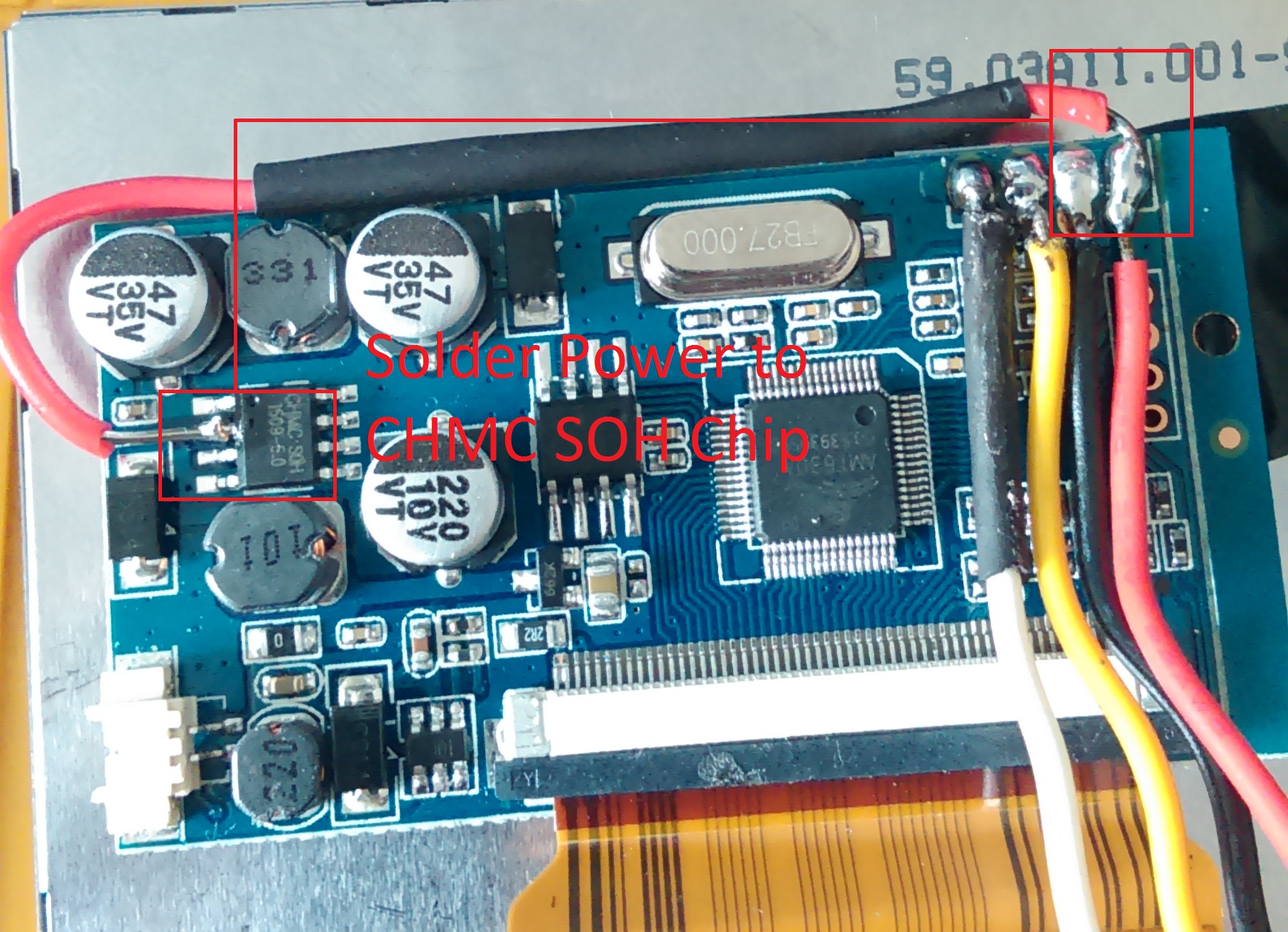
While, technically, the BW7 display works without modifications, my experience was that it had very noticeable flickering when used that way. I'd really recommend soldering a jumper wire like so:
Thank you for the help, I think I will go with you and do option 3. Final question what gauge wire is best to use for 1) the control connecions - dpad 2) general connections and 3) powered connections?RxBrad wrote:@Rog585
Keep the red wire attached to the board as it is. The jumper wire is soldered onto the same solder point as the existing wire, and onto the pin shown on the IC.
This post shows a basic breakdown of the wiring that most people use.
Red and white go to the Powerboost.
Yellow goes to the "TV" through hole on the Pi0.
Many people use the white wire as the ground, and simply wire it to the through-hole next to the "TV" on the Pi0. The thing is, the white wire is technically the AV2 input wire for the screen. Others have simply snipped the white wire off and left it unused, and don't attach anything next to the "TV" through-hole (this is the ground wire for the TV input, BTW). I don't know the right way to do it, but apparently both ways work.
A third option that makes more sense to me is to completely remove the white wire, then solder it onto the same pad as the black wire on the screen PCB. Then solder the other end of the white wire to the through-hole next to "TV" on the Pi0. (If you tear apart the factory-attached cable for the screen, you'll see that this is how they handle grounding the AV inputs, assuming they don't have any special components hidden away in the joint where the red/white/yellow cables split off.)
Starting to get off-topic for this thread, but I used 30AWG for controls and stuff going into regular old GPIOs. I used 22-26AWG for powered/audio connections. Others will have different answers to this. Might want to start another thread (or see if one exists) if you want further info.Rog585 wrote:Thank you for the help, I think I will go with you and do option 3. Final question what gauge wire is best to use for 1) the control connecions - dpad 2) general connections and 3) powered connections?
That's perfect, you have been a great help and will give it a go, just to confirm for option 3 the white wire should go through the hole to the right of tv which is marked up as U3?RxBrad wrote:Starting to get off-topic for this thread, but I used 30AWG for controls and stuff going into regular old GPIOs. I used 22-26AWG for powered/audio connections. Others will have different answers to this. Might want to start another thread (or see if one exists) if you want further info.Rog585 wrote:Thank you for the help, I think I will go with you and do option 3. Final question what gauge wire is best to use for 1) the control connecions - dpad 2) general connections and 3) powered connections?
Yup. On the Pi0, TV output and the ground for TV output have the little white box around them. (like you, I think the U3 refers to the ground pin, but the label is placed kind of funny, so it might technically refer to a component(s) under it).Rog585 wrote: That's perfect, you have been a great help and will give it a go, just to confirm for option 3 the white wire should go through the hole to the right of tv which is marked up as U3?
Users browsing this forum: No registered users and 1 guest