Page 1 of 2
BW 3.5" Composite Display - Variant 2
Posted: Thu Jun 16, 2016 9:06 am
by gnarlynick
Hello,
I purchased variant 2 of the BW 3.5" Composite Display and was able to solder the one wire from the IC to the power on the PCB to convert it to 5V and it is running fine wired to my Pi Zero.
[spoiler="Display board for that variant"]

- Bwv2jumper.jpg (906.35 KiB) Viewed 12343 times
[/spoiler]
Problem is, the contrast is a bit high and it doesn't have a button board to adjust brightness/contrast out of the box.
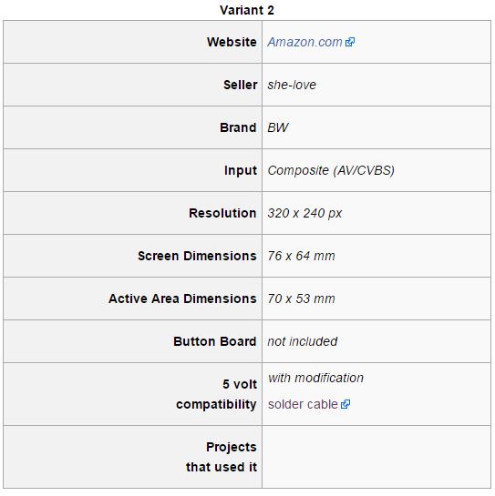
- Capture.JPG (41.07 KiB) Viewed 12343 times
Does anybody who knows more about this than me know if there is a way I can wire some sort of brightness/contrast tac buttons to the display control board? I would assume there's somewhere on there I can tap into to create a tac button breakout board like the other screens have.
Re: BW 3.5" Composite Display - Variant 2
Posted: Thu Jun 16, 2016 9:11 am
by gnarlynick
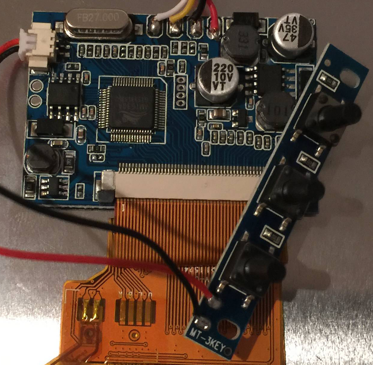
I see on brettygud_'s GBZ project (he is using variant 4 of the BW 3.5" display) that his display control board is identical to mine but he has a breakout board attached to the white JST looking port on the upper left side. My board has that port as well but did not come with a breakout board. Photo below is from brettygud_'s GBZ project thread.
[spoiler="Image courtesy of brettygud_"]
- l15CzuH.jpg (742.47 KiB) Viewed 12342 times
[/spoiler]
Am I correct in thinking that I can solder together a tac button breakout board much like wermy does in his 2nd tutorial for the Adafruit screen and solder the +/- wires from it to that JST looking connection port on the display control board? I will try this when I get a chance. I would like to be able to adjust the contrast/brightness at least once to dial it in so it looks good.
Re: BW 3.5" Composite Display - Variant 2
Posted: Fri Jun 17, 2016 1:41 am
by Fleder
If you wire those correctly, you could even just use 2 wires and connect them for a short time to imitate a pressed button.
Just be sure to use a multimeter first, so you do not damage your board.
Re: BW 3.5" Composite Display - Variant 2
Posted: Fri Jun 17, 2016 6:27 pm
by gnarlynick
Fleder wrote:If you wire those correctly, you could even just use 2 wires and connect them for a short time to imitate a pressed button.
Just be sure to use a multimeter first, so you do not damage your board.
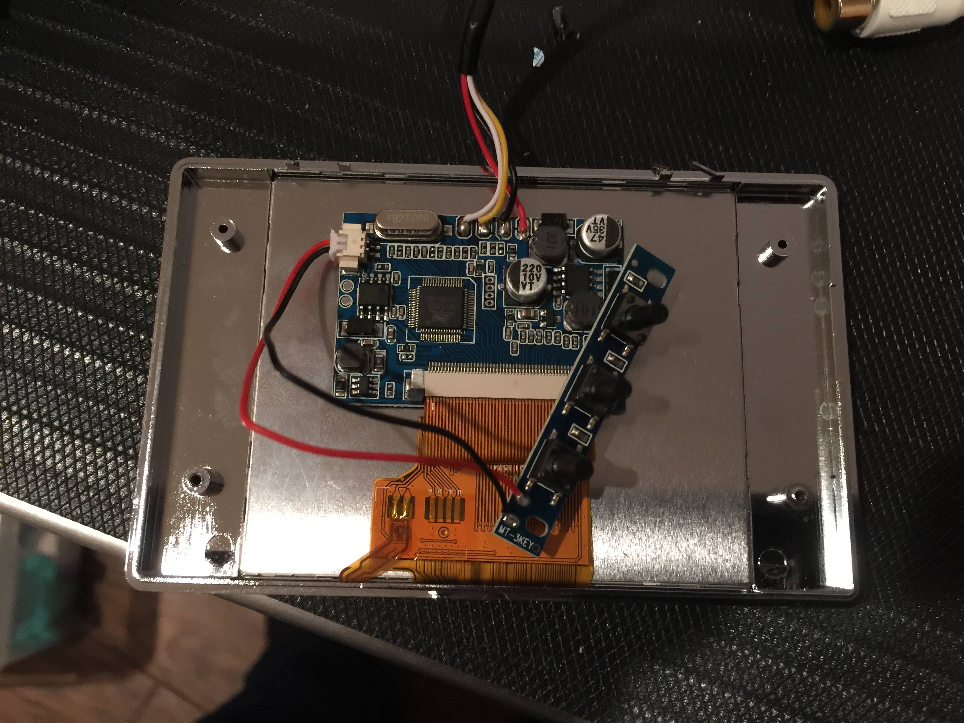
There must be more to it than just connecting a switch. I made a whole 3 button breakout board and attached it to the +/- pins there and nothing registered with button presses. I then simplified it and wired 1 button directly to it and still nothing. [spoiler="Does anybody here have anymore insight on how to add a button board"]

- 1466209535709-1335591880.jpg (5.44 MiB) Viewed 12260 times
[/spoiler]
Re: BW 3.5" Composite Display - Variant 2
Posted: Fri Jun 17, 2016 6:50 pm
by DirtyBullets
check the button wiring cos its wrong. you need to solder the button ether pins 1 and 3 or 2 and 4 not 1 and 4 or 2 and 3 like yours if you get what i mean on that tact switch (i did similler thing to one of my projects)
Re: BW 3.5" Composite Display - Variant 2
Posted: Fri Jun 17, 2016 8:07 pm
by gnarlynick
DirtyBullets wrote:check the button wiring cos its wrong. you need to solder the button ether pins 1 and 3 or 2 and 4 not 1 and 4 or 2 and 3 like yours if you get what i mean on that tact switch (i did similler thing to one of my projects)
Thanks for the info, I will try that.
Re: BW 3.5" Composite Display - Variant 2
Posted: Sat Jun 18, 2016 1:50 am
by Popcorn
It must be triggered by different resistance per each button or else how can you register three to four different buttons on 2 wires?
PS: I had (and have ordered another of) this exact board so if you figure it out, let us know!

Re: BW 3.5" Composite Display - Variant 2
Posted: Sat Jun 18, 2016 2:25 am
by Moxide
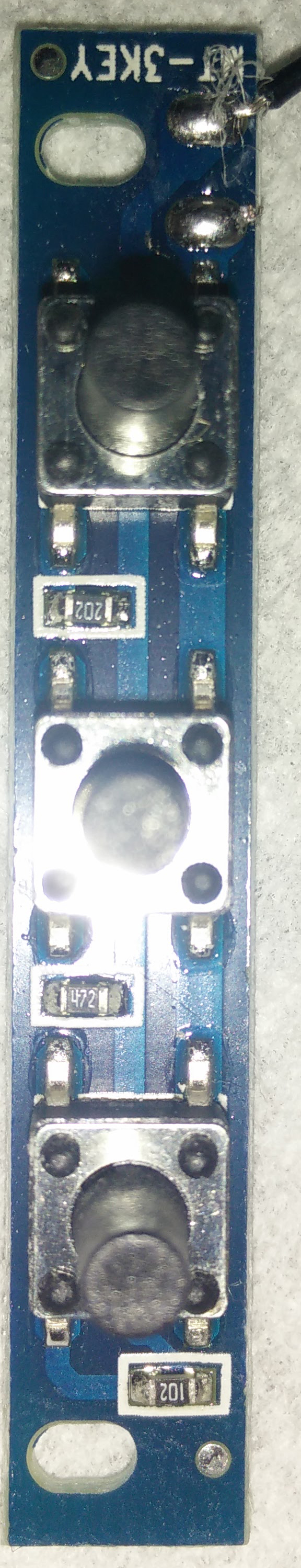
I have this board, Looks like it connects the positive down all three, goes into the 102 SMD resistor through the negative off the last button, 472 SMD resistor before the second button, then a 202 SMD resistor between the first button.
Link to the image, you can zoom in on it.
https://goo.gl/photos/XEXN41P87UiyW2Cj9
Re: BW 3.5" Composite Display - Variant 2
Posted: Sat Jun 18, 2016 9:02 am
by gnarlynick
Popcorn wrote:It must be triggered by different resistance per each button or else how can you register three to four different buttons on 2 wires?
PS: I had (and have ordered another of) this exact board so if you figure it out, let us know!
Moxide wrote:I have this board, Looks like it connects the positive down all three, goes into the 102 SMD resistor through the negative off the last button, 472 SMD resistor before the second button, then a 202 SMD resistor between the first button.
I was wondering how it differentiates between button presses since they all tie into 2 wires in the end. Looking at the photo of the button board on the other variant it looks like it has resistors on each button to change the resistance registered with each press.
[spoiler="Button Board Closeups"]
- l15CzuH.jpg (1006.54 KiB) Viewed 12194 times
Special thanks to Moxide for the closeup photo below:
- l15Czu.jpg (1.02 MiB) Viewed 12190 times
[/spoiler]
Re: BW 3.5" Composite Display - Variant 2
Posted: Sat Jun 18, 2016 9:11 am
by gnarlynick
It shouldn't be too difficult to wire up a button board circuit mirroring this; complete with the appropriate resistors. Can anybody WITH a working button board verify that when you change the contrast/brightness settings, do they retain between power cycles?
I don't really care to be able to adjust the settings on the fly and don't see this happening too often, if at all. I'd rather just save space inside the shell and not include a button board in the final build. I just want to make one board and fine tune all the GBZ projects I am working on by momentarily attaching that board to the display control board and adjusting the video output. If the settings aren't retained through power cycles though, this changes that thinking...