[WIP] Game Boy Color AIO Board
Posted: Thu Jan 03, 2019 9:45 am
Hi all!
I'm new at the forums and this is going to be my first post, so first of all, hello everyone!
I have an old Game Boy Color lying arround, but sadly it doesn't work, so I want to make a Game Boy Color Zero with the raspberry that I have.
Unfortunately, I couldn't find any AIO board for the Color version, so I have to do my own.
It's based in the post: https://www.sudomod.com/forum/viewtopic.php?f=42&t=6499
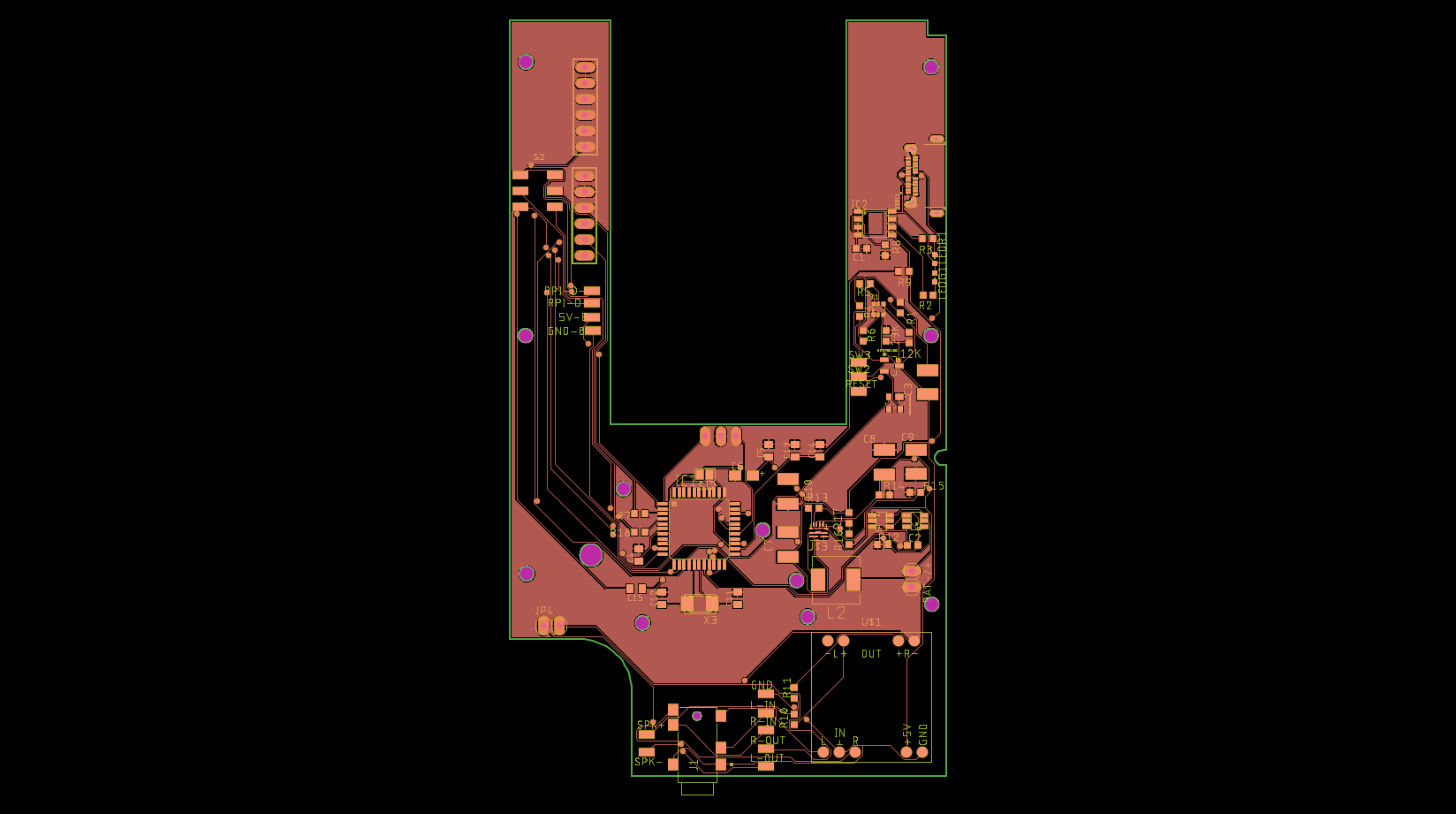
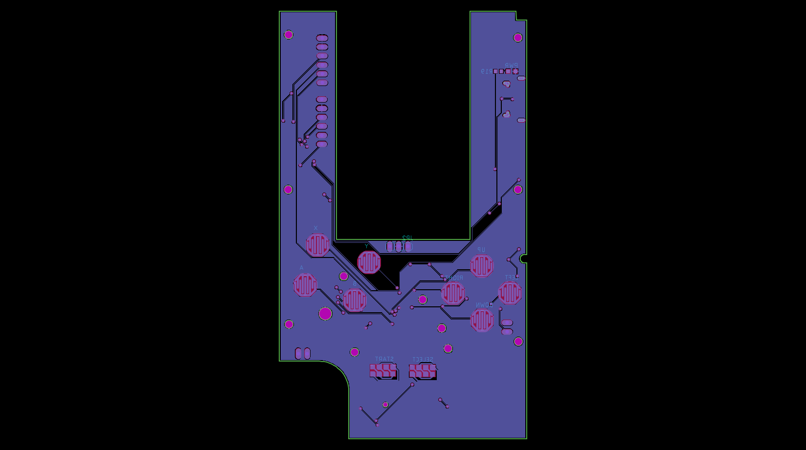
I ended up with something like this
 So, the changes that I made was:
And the changes that I want to add:
But I need a little bit of help. First of all, I'm not used to do PCBs, so I'm sure there are errors. Second, I don't know how to add a screen. I left space in the PCB for one, but I want to add the controll circuit for the screen, and I couldn't find anything about this.
So, the changes that I made was:
And the changes that I want to add:
But I need a little bit of help. First of all, I'm not used to do PCBs, so I'm sure there are errors. Second, I don't know how to add a screen. I left space in the PCB for one, but I want to add the controll circuit for the screen, and I couldn't find anything about this.
So, thats all! I left my board and schematic (schematic is almost the same that the rlcmtzc12's post) so anyone can see/modify the design.
https://github.com/miguellahoz/Game-Boy-Color-AIO
Thank you all!
Edit 1:
So, I changed how I can do some things, so first of all I'm going to post here all the circuits that I have my board to have, what IC's I want to use and, when I have it designed, the schematics.
Also, I'm going to change the input system, so it uses the GPIO pins of the Raspberry instead of the USB port.
And I also added a folder in the github with the PCB design empty with the screws holes for the GBC.
I'm new at the forums and this is going to be my first post, so first of all, hello everyone!
I have an old Game Boy Color lying arround, but sadly it doesn't work, so I want to make a Game Boy Color Zero with the raspberry that I have.
Unfortunately, I couldn't find any AIO board for the Color version, so I have to do my own.
It's based in the post: https://www.sudomod.com/forum/viewtopic.php?f=42&t=6499
I ended up with something like this
PicsShow
ChangesShow
- Added L/R buttons
- Added a programming and a bootloader connectors to burn the bootloader or programm the ATMEGA chip
TODOShow
- Change the battery protection circuit to allow for 2 1.5V batteries, so they can be put in the battery holder of the GBC
- Change the audio amp board for an in-board design
- On-screen battery indicator based on https://learn.adafruit.com/adafruit-ina ... e?view=all
- Support for a screen
So, thats all! I left my board and schematic (schematic is almost the same that the rlcmtzc12's post) so anyone can see/modify the design.
https://github.com/miguellahoz/Game-Boy-Color-AIO
Thank you all!
Edit 1:
So, I changed how I can do some things, so first of all I'm going to post here all the circuits that I have my board to have, what IC's I want to use and, when I have it designed, the schematics.
Also, I'm going to change the input system, so it uses the GPIO pins of the Raspberry instead of the USB port.
And I also added a folder in the github with the PCB design empty with the screws holes for the GBC.
Battery Protection CircuitShow
I'm planning to use a Li-Po battery, I was thinking about this one: http://www.crazell.com/product/703048/.
This batteries usually comes with their own protection circuit, so I don't need one in the board.
This batteries usually comes with their own protection circuit, so I don't need one in the board.
Boost circuit (Step up/down)Show
We have a battery that could give 4.2V to 3.7V, we need to boost this voltage to 5V.
The best IC that I could find is the TPS61240.
Data and datasheet: http://www.ti.com/product/tps61240
The best IC that I could find is the TPS61240.
Data and datasheet: http://www.ti.com/product/tps61240
Charging circuitShow
Actually, I'm using a circuit based in the TC4056A, and it works fine, so I'm looking for another ICs, but this one seems fine.
WIP
WIP
ShutDown CircuitShow
A circuit that shuts down the Rapsberry when low battery is detected. It could be done with a detector IC, with the boost circuit (for some ICs), or with programming if it's a software battery level indicator
AudioShow
I need a circuit that can amplify audio, and turn off the speaker when a headphone is detected.
ScreenShow
I'm still looking for a screen that fits, the maximum size is arround 55.8 x 57 mm, maybe a little more if we don't keep the power indicator in the screen, it becomes 56 x 65.8 mm.