Kyles first project

Show off your completed Game Boy Zero, or post your build logs here!
User avatar
CaptainDurden
Posts: 133
Joined: Wed Sep 07, 2016 1:24 pm
Has thanked: 70 times
Been thanked: 48 times

Re: Kyles first project

Post by CaptainDurden » Tue Oct 11, 2016 6:25 pm

i fucked up my first case completely with a dremel, thing kept slipping out of control, randomly touching the sides and even the outside of the case leaving bad marks everywhere and finally leaving a proper cut in the side. that almost made me abandon the entire project to be honest.

i got another case and some proper name brand tool bits for the cheap knock off dremel tool (especially the diamond cutting disc made a huge difference) and very slowly and deliberately planned my approach cut by cut, then proceeded to smooth the edges with a grinding bit and finally polished the cuts with reeeeaaaaaally fine sanding paper. the screen cut-out i did with an x-acto knife, that gave me more control to leave an edge which i can glue the screen protector to later. it's by no means perfect but at least i still have the bottom screw holes and no visible blemishes on the outside. for me what worked best is putting the dremel to maximum rotation but doing short and precise cuts so the plastic doesnt get to hot and starts burning. melting is fine, smoking, burning and discoloring is no-no's.

the button holes i did with a step drill bit but since i neither have a drill press nor a proper torque wrench to hold the bit i actually twisted it into the case by hand, bit by bit. the result was 2 surprisingly good looking button holes and three bloody cuts on my fingers from gripping the drill bit so hard.

so as you can see, i'm very noob to all this myself, the most important thing i learned so far is "take it slow, measure twice, cut once"
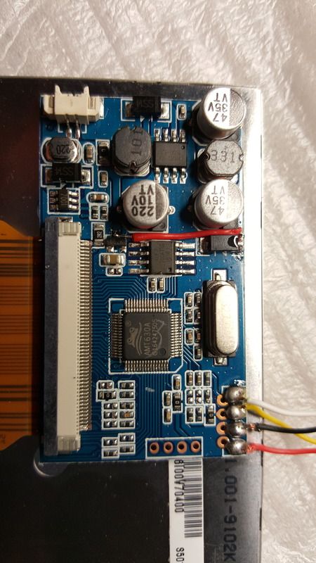
here's some pics:
[spoiler="careful, large, will slow your browser down"]ImageImageImageImageImage[/spoiler]
Helder wrote:People spend so much time in asking questions and no time looking for an answer that is available.

kylepiboy
Posts: 27
Joined: Tue Oct 04, 2016 3:15 pm
Has thanked: 1 time

Re: Kyles first project

Post by kylepiboy » Tue Oct 11, 2016 7:39 pm

Looks great! How does the screen fit with the top screw hold downs still in place?

User avatar
CaptainDurden
Posts: 133
Joined: Wed Sep 07, 2016 1:24 pm
Has thanked: 70 times
Been thanked: 48 times

Re: Kyles first project

Post by CaptainDurden » Tue Oct 11, 2016 7:45 pm

i removed the top screw posts, but will use one of wermy's 3d printed screw brackets in order to still properly lock the case.

look here:

http://www.sudomod.com/forum/viewtopic.php?f=3&t=789

you just glue it on top of the screen, pretty ingenious. you can order one from wermy or just use his stl file and print it yourself/ get it printed somewhere.
Helder wrote:People spend so much time in asking questions and no time looking for an answer that is available.

kylepiboy
Posts: 27
Joined: Tue Oct 04, 2016 3:15 pm
Has thanked: 1 time

Re: Kyles first project

Post by kylepiboy » Wed Oct 12, 2016 8:02 am

Okay awesome. I have an extra case in case I need it but I'm going to see how this goes haha.

Also how do you program the buttons with the teeny? Looks like everyone uses them, but I can't find anything about the details.

User avatar
CaptainDurden
Posts: 133
Joined: Wed Sep 07, 2016 1:24 pm
Has thanked: 70 times
Been thanked: 48 times

Re: Kyles first project

Post by CaptainDurden » Wed Oct 12, 2016 8:06 am

I couldn't tell you since I'll be using AIO boards in my builds, but the forum search is your friend, you should get to know it better.
Helder wrote:People spend so much time in asking questions and no time looking for an answer that is available.

kylepiboy
Posts: 27
Joined: Tue Oct 04, 2016 3:15 pm
Has thanked: 1 time

Re: Kyles first project

Post by kylepiboy » Sat Oct 22, 2016 12:31 pm

Okay so I've been waiting on parts and thinking about everything to do; and I've decided to redo my case haha
IMG_2656.JPG
IMG_2656.JPG (1.37 MiB) Viewed 8587 times
IMG_2655.JPG
IMG_2655.JPG (1.28 MiB) Viewed 8587 times
Next I got my screen today but can't figure out how to make it work on 5v. I've been looking on here with search and googled it but can't find my exact board. Any help on it would be great
IMG_2663.JPG
IMG_2663.JPG (1.63 MiB) Viewed 8587 times

Justblair
Posts: 21
Joined: Wed Oct 05, 2016 7:48 am
Location: Glasgow, Scotland
Has thanked: 3 times
Been thanked: 5 times
Contact:

Re: Kyles first project

Post by Justblair » Sat Oct 22, 2016 12:47 pm

Image

Justblair
Posts: 21
Joined: Wed Oct 05, 2016 7:48 am
Location: Glasgow, Scotland
Has thanked: 3 times
Been thanked: 5 times
Contact:

Re: Kyles first project

Post by Justblair » Sat Oct 22, 2016 12:47 pm

http://sudomod.com/wiki/index.php?title ... AG0115.jpg

Have a look at htis in the wiki. This is your board. I have just been working on the same board, I have not tested it yet, but I did mine like this...

Image[/URL]

kylepiboy
Posts: 27
Joined: Tue Oct 04, 2016 3:15 pm
Has thanked: 1 time

Re: Kyles first project

Post by kylepiboy » Sat Oct 22, 2016 4:50 pm

Justblair wrote:http://sudomod.com/wiki/index.php?title ... AG0115.jpg

Have a look at htis in the wiki. This is your board. I have just been working on the same board, I have not tested it yet, but I did mine like this...

Image[/URL]

Awesome!! Thank you! I'll try both methods.

Justblair
Posts: 21
Joined: Wed Oct 05, 2016 7:48 am
Location: Glasgow, Scotland
Has thanked: 3 times
Been thanked: 5 times
Contact:

Re: Kyles first project

Post by Justblair » Sun Oct 23, 2016 5:12 am

I have tested mine now and I can confirm the photo I posted works. It's not in the wiki but I think it is slightly neater.

The red wire is attached to the anode of the diode (right of screen) on one end and the input to the 3.3v voltage regulator (marked 662K).

It does exactly the same job as the wiki is doing, but just at a little more convenient part of the circuit.

Post Reply

Who is online

Users browsing this forum: No registered users and 1 guest