Raspberry Pi 4 old new build

Show off your completed Game Boy Zero, or post your build logs here!
Post Reply
MaxPof
Posts: 6
Joined: Tue Jun 02, 2020 6:02 am
Been thanked: 1 time

Raspberry Pi 4 old new build

Post by MaxPof » Tue Jun 02, 2020 8:35 am

Hi!

I finally 'finished' my first build. I started this nearly 3 years ago: Everything was almost set up but... well I didn't take the time to finish it and I was never entirely satisfied to finally close this project and I ended up forgetting this project in a box.

But these last months I have had a lot of time and I was able to start this project again. My initial goal was to be able to play N64 and PS1 games. At this time, the last available RPi was the 3b+, so this is what I used. I didn't play a lot with it but I try to launch Zelda OOT, the game was running pretty well on it but I had some concerns ( the start menu which took more than 5 seconds to appear for exemple) so I had a lot of doubt about the possibility of playing PS1 games

And when I started this project again last month, I had a RPI4 4gb on hand... And Retropie had just updated for RPi4... I hesitated for a long time considering the difficulty I had in unsolder all the components of the rpi3, but after trying OOT with it and seeing that the start menu was very fluid, I started over!

So this second build is a little bit less... neat... I didn't have the same patience to start over the desolder so I do it faster and didn't try to keep the connector reusable this time. Also, the hot glue gun that I had carefully avoided the first time appeared a little bit...

So here are the pictures: (I haven't yet solder the PAM for now, and the glass screen neither, have to fix that and some other things...)

Image
Image
Image
Image

Image
Image


-L and R trigger and joystick from old slim PSP
-Power switch from PSP -> on-on-(on) switch, I use the last astable 'on' to safe shutdown using SotaSystems script (see link after)
-Digital sound (because it's not easy to add analog potentiometer to control sound level with the PAM8403, explanations later)
-RGB led for charging and low batterie status (logic required with Adafruit 1000C powerBoost)
-3.5 LCD RCA from rear camera
-USB C charging (because USB micro is so 2010...)

Things have changed a lot since I started, today there are a lot of ready-made modules that would greatly simplify construction, but I didn't want to change everything...

First, a huuuuge thanks to Sotasystems (I think he is on this forum, no sure) I mainly follow his project to build mine and this help me a lot!
https://hackaday.io/project/18003/instructions
Same thing for Veteran's builds:
viewtopic.php?f=43&t=3392

For the sound wiring, I try some diagram I found on Veteran's build (those two here). I have some bad result with the second one. In fact, I think you cannot shortcut the two negative wire of R and L channel. those two are meant to be separated (see datasheet, two separated driver for each channel). If I remember well, there is a way to do it properly with a single potentiometer , but I can't find the schematic...
Or use a 2 channel potentiometer, but I don't know if you can find it in wheel format....

So to simplify it, I've just used a digital potentiometer (or encoding wheel), basically, I used the wheel from an old mouse and used this:
https://gist.github.com/savetheclocktow ... tor-volume
I plug my headphone directly at the output of the raspberry (it's made for that) and the PAM8403 is after the headphone connector, only for the speaker. And the volume is controlled directly by the RPI.
Image

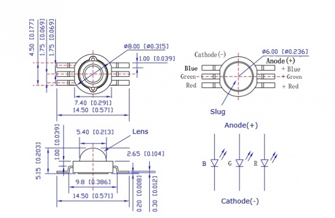
For the LED, I wanted to replace the LEDs of the Adafruit module with a single 5mm LED. But If you check the schematic, it is not possible to replace them with a common anode or cathode led. So either use NOT gates to change the logic of the LEDs, or use a RGB LED with separate anode and cathode like this.
(Be carful, it's not because it's a 6 pin LED that it has separate anode and cathode:
http://lednique.com/leds-with-more-than ... in-pinout/ )

I used SMD NOT gates, it really doesn't take up much space:
Image

I have some issues with my screen. First there is a lot of flickering on bright images. I know It's a cheap 12v screen that I use in 5v, but It's almost unplayable... It's a very fast and constant flicker (like 50hz or more) you all have this problem or my screen is very crappy?
I can't find the same control board in the wiki, but it looks a lot like the others:
Image
And the resolution is very very bad! I managed to have something readable on the terminal and on Retropie by following this method and changing the theme.
But the retropie menu and the games are practically illegible:
Image
(a dialog in Zelda OOT)
Do you think I have to change to an HDMI or does mine just suck?

User avatar
infinitLoop
Posts: 536
Joined: Mon Dec 24, 2018 11:46 am
Location: Portland, OR
Has thanked: 222 times
Been thanked: 199 times
Contact:

Re: Raspberry Pi 4 old new build

Post by infinitLoop » Tue Jun 02, 2020 10:22 am

those screens are terrible - i think you might be out of luck with that. if you look around for the model listed as "2 - ch real color 3.5 inch tft lcd display monitor module" which people tended to call the "gearbest" version, that has about as good quality as you're going to get with those composite screens. they run aroun 15-30

i wouldn't recommend hdmi, personally - the control boards and screens are usually just a bit too large to fit in a dmg case anymore. you can find some sometimes that *just* fit if you shave the sides down, but it's extremely tight.

if you wouldn't mind, i'd like some more details on how you wired up that gate for the LEDs, since that's something i wanted to solve for, but haven't yet.


.

Dividion
Posts: 95
Joined: Fri Mar 30, 2018 5:42 am
Has thanked: 58 times
Been thanked: 69 times

Re: Raspberry Pi 4 old new build

Post by Dividion » Tue Jun 02, 2020 10:58 am

Nice to see a build using the Pi4. I read that the Pi4 has to run with slower clock speeds in order to support composite, so it disables it by default. I imagine you re-enabled it in raspi-config or the config.txt file. Good to know that it still runs plenty fast for games, but I wonder if that's part of the issue with the screen flickering. Switching to a DPI or SPI display would probably help, if you have the GPIO pins available, which it looks like you should since you're using a microcontroller for the controls. Those are more crisp and not nearly as power-hungry as HDMI, but swapping one in there will probably take a bit of work at this point.
Check out my store for GBZ boards and accessories: http://pocketadventures.com

MaxPof
Posts: 6
Joined: Tue Jun 02, 2020 6:02 am
Been thanked: 1 time

Re: Raspberry Pi 4 old new build

Post by MaxPof » Wed Jun 03, 2020 11:06 am

if you wouldn't mind, i'd like some more details on how you wired up that gate for the LEDs, since that's something i wanted to solve for, but haven't yet.
Well, nothing hard:
In my case I only have a common cathode RGB LED, so if you check the schematic:
https://learn.adafruit.com/assets/24638
It will be ok for the LED1 because it directly connected to the ground, but not for CHARGE/LBO LED and DONE LED (I don't use LED2).
Because those two led's anode are constantly connected to 5V, this means that to turn on the led, the signal at the output of MCP73871 must be 0V, and to shutdown the led, the signal must be equal on both anode and cathode side, so 5V.
So the MCP73871 behavior is LED ON=> 0V, LED OFF => 5V and we want the opposite to connecte a LED between the output and the ground...
A NOT gate just invert the signal: if you put something above the threshold (let's say 5V) the output will be 0V; And if you put 0V to the input, the output will be equal to the supply voltage of your gate.
The good thing is that if you connect your gate instead of one of the leds of the circuit, the signal will be high enough above the threshold to trigger the gate. So you just connect your gate instead of the LED you want to change the polarity, power your gate (see the datasheet of your gate and take one who accepte 5V power supply). And connect your LED between the output of your gate and the ground WITH A RESISTOR!!!! Don't think that the resistors R8 and R14 of the circuit limit the current in your led, at the gate output you have the supply level, with no current limit (except the one of your gate, if this one don't burn...) so put a resistor!

Sorry, I don't have any schematic software to do the wiring, but you can do it, it's really easy!
I read that the Pi4 has to run with slower clock speeds in order to support composite, so it disables it by default. I imagine you re-enabled it in raspi-config or the config.txt file
Yup, see here:
https://www.raspberrypi.org/documentati ... t/video.md
"enable_tvout (Pi 4B only)"

My config.txt file looks like this:

Code: Select all

disable_overscan=0
overscan_scale=1

overscan_left=10
overscan_right=10
overscan_top=10
overscan_bottom=10

framebuffer_width=320
framebuffer_height=240

display_rotate=2
enable_tvout=1
but I wonder if that's part of the issue with the screen flickering
Nope, I had the same problem with my RPi 3B+
Switching to a DPI or SPI display would probably help, if you have the GPIO pins available, which it looks like you should since you're using a microcontroller for the controls. Those are more crisp and not nearly as power-hungry as HDMI, but swapping one in there will probably take a bit of work at this point.
Thanks, I will look at it!

Post Reply

Who is online

Users browsing this forum: No registered users and 1 guest