Page 1 of 2
Modification of screen to use 5V
Posted: Thu Mar 01, 2018 6:42 am
by MrLuck
Hello there,
I have seen the beautiful work that this community has done and aswell seen the list of screens made to be used with 5 V. I ordered myself a 4.3" 480 x 272 px (I know it won't fit the regular Game Boy casing, but I have a 3D printed case I made myself. However it doesn't seem to want to work with 12V (Tested using a GameCube as a composite video signal) The board is quite small and my best guess is to solder positive and negative respectivly to the schottsky diode. However I am no expert and would like a second opinion, can anyone see a better way of making this board work with 5V?
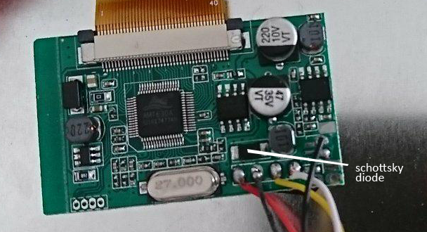
- board.png (324.32 KiB) Viewed 7339 times
Re: Modification of screen to use 5V
Posted: Thu Mar 01, 2018 7:14 am
by VeteranGamer
MrLuck wrote: ↑Thu Mar 01, 2018 6:42 am
Hello there,
I have seen the beautiful work that this community has done and aswell seen the list of screens made to be used with 5 V. I ordered myself a 4.3" 480 x 272 px (I know it won't fit the regular Game Boy casing, but I have a 3D printed case I made myself. However it doesn't seem to want to work with 12V (Tested using a GameCube as a composite video signal) The board is quite small and my best guess is to solder positive and negative respectivly to the schottsky diode. However I am no expert and would like a second opinion, can anyone see a better way of making this board work with 5V?

you need to sort the image out....
either upload as an attachemnt...
or use the BBCode link to paste your image from imgur....
i've done it here for you....

.
Re: Modification of screen to use 5V
Posted: Thu Mar 01, 2018 7:49 am
by MrLuck
Thank you VeteranGamer was a bit to quick on my post there.
Re: Modification of screen to use 5V
Posted: Thu Mar 01, 2018 7:50 am
by VeteranGamer
MrLuck wrote: ↑Thu Mar 01, 2018 7:49 am
Thank you VeteranGamer was a bit to quick on my post there.
it may also be a good idea to provide a bit more info about the screen....
what screen is it....
and maybe a link....
.
Re: Modification of screen to use 5V
Posted: Thu Mar 01, 2018 8:04 am
by MrLuck
The screen what purchased on this swedish site:
https://fyndiq.se/search/?q=backkamera& ... backkamera
There is not much information on the brand what so ever. The box it came in simply says car security camera. The board runs a AMT630A and has one other labled chip directly to the right of the AMT chip. Its a bit blurry even with a magnifying glass but it says something like:
BergMiore
25Q40ASNG
1704
The ribbon cable has some values written on them as follows:
ZNL043T702-P40
JGY
And the screen itself has the following on the back of it:
RT43WH006A
RGH160531
The text on the ribbon cable leads me to beliave that it is a Dong-Hua 4.3" screen. But it has not yet lead me to any conclusions about the driver board.
Re: Modification of screen to use 5V
Posted: Thu Mar 01, 2018 8:59 am
by VeteranGamer
MrLuck wrote: ↑Thu Mar 01, 2018 8:04 am
The screen what purchased on this swedish site:
https://fyndiq.se/search/?q=backkamera& ... backkamera
There is not much information on the brand what so ever. The box it came in simply says car security camera. The board runs a AMT630A and has one other labled chip directly to the right of the AMT chip. Its a bit blurry even with a magnifying glass but it says something like:
BergMiore
25Q40ASNG
1704
The ribbon cable has some values written on them as follows:
ZNL043T702-P40
JGY
And the screen itself has the following on the back of it:
RT43WH006A
RGH160531
The text on the ribbon cable leads me to beliave that it is a Dong-Hua 4.3" screen. But it has not yet lead me to any conclusions about the driver board.
can you provide a clearer image of the board...
especially of the 2 chips located near the diode you highlighted....
.
Re: Modification of screen to use 5V
Posted: Thu Mar 01, 2018 9:50 am
by MrLuck
Absolutley, here is a better image
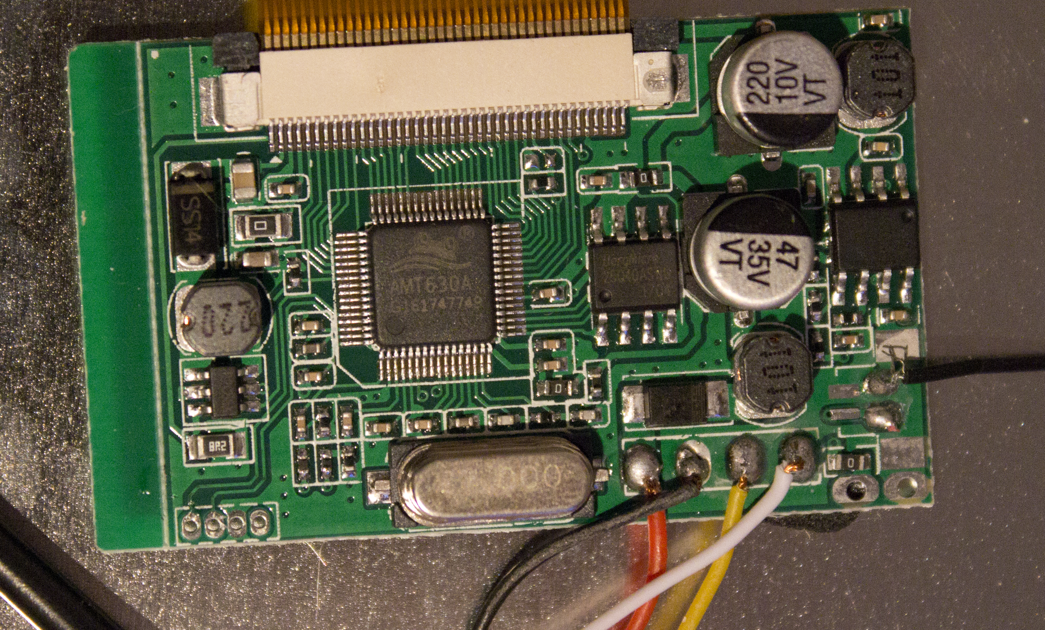
- board.jpg (7.97 MiB) Viewed 7331 times
The PNG version was to big to upload, but I hope this jpeg does the job aswell.
PS I know that there is a red wire missing on the right next to the black wire, they are the connections to the buttons for screen settings.
Re: Modification of screen to use 5V
Posted: Thu Mar 01, 2018 12:39 pm
by jakejm79
You'll need the test off the two 8 pin ICs, that said you could probably get away with soldering to the +ve side of the capacitor marked 10V.
Re: Modification of screen to use 5V
Posted: Thu Mar 08, 2018 2:53 pm
by Hex
In case you are still looking for a solution:
See the 4 pads on the bottom left corner? the first pin from right is 3.3V and the second is GND. those are the only 2 pins you need to power the display. Then just connect a yellow or white wire to the Pi and you will have a working lcd
Here is another board that has a similar IC and the 4 pin.

Re: Modification of screen to use 5V
Posted: Fri Mar 09, 2018 11:49 am
by Wailer
.