Page 1 of 1
Display identification help
Posted: Sat Mar 10, 2018 10:43 pm
by Macromun
I just got the majority of my GBZ parts (my first build) and I got a variant of the board that isn't on the wiki...

- the board in question
- IMG_20180310_234018944_LL.jpg (192.32 KiB) Viewed 3477 times
If I could get some help on this, it would be much appreciated!

Re: Display identification help
Posted: Sun Mar 11, 2018 12:44 pm
by Mario.Semiglia
Hallo,
if you have a multimeter you could track where the multimeter reads 5v...
I am not really shure but I think you should try tracking where the power of this 470 resistor is going...
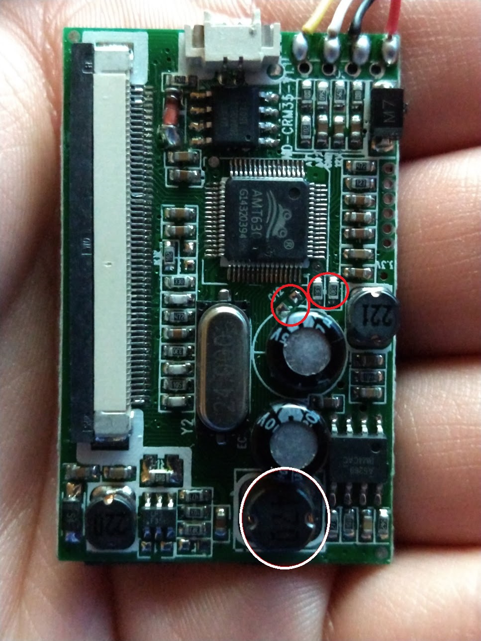
- IMG_20180310_234018944_LL.jpg (302.06 KiB) Viewed 3462 times
I would try to make a bridge with the miltimeter between your red wire and the places at I marked red first
other wise I dont know
Re: Display identification help
Posted: Sun Mar 11, 2018 2:43 pm
by Wailer
Question: have you tried running it at 5v?
Just feed it power and a video signal, if works it could save you a lot of time.
Otherwise you have to identify the regulator chip, wich in your case, could be the 8pin chip in the bottom of the picture (i could not identify it for you, the picture is not sharp enough

).
Once identified it shouldn't be to hard to find a datasheet.
The chip next to the vid controller chip is a data storage chip (in most cases).
Re: Display identification help
Posted: Sun Mar 11, 2018 4:22 pm
by Macromun
the chip name is wd-crm35-V1.1 if that helps at all
Update:
Here's a picture of the back, if that helps.
It isn't working on 5v (makes sense reading the back)
Re: Display identification help
Posted: Thu Mar 14, 2019 7:22 pm
by T33Hud
Digging up bones here... I have the same screen and board, which ran fine on 5v for a while. Now I get a screen with cycling colors instead of the signal from the pi. I've tested the pi with another screen, everything works fine so I'm trying to track down any info I can about the screen's current issue. I took detailed shots of the two 8 legged chips, but as far as multimeter testing wouldn't know where to start. Any and all help welcome.

edit: I was able to fix the board based on the suggestion by Ummi in this thread:
viewtopic.php?f=42&p=20997#p20997
You need to run a line from the second leg of chip 2 referenced above. Here is a shot of the fix on my board:
