Page 1 of 2
Help with BW screen
Posted: Mon Apr 02, 2018 5:04 pm
by Nealon
Hello! I ordered one of those 3.5 inch BW screens off of amazon and took it apart, but the board doesn't seem to exactly match any of the variants on the wiki. I'm very new to this stuff and this is my first project of this sort. So I'm wondering what I need to do to make it work with the pi zero and if I need to do anything to make it 5v ready.
If i had to guess, it looks kind of close to variant #8, so I could treat this board as the same?
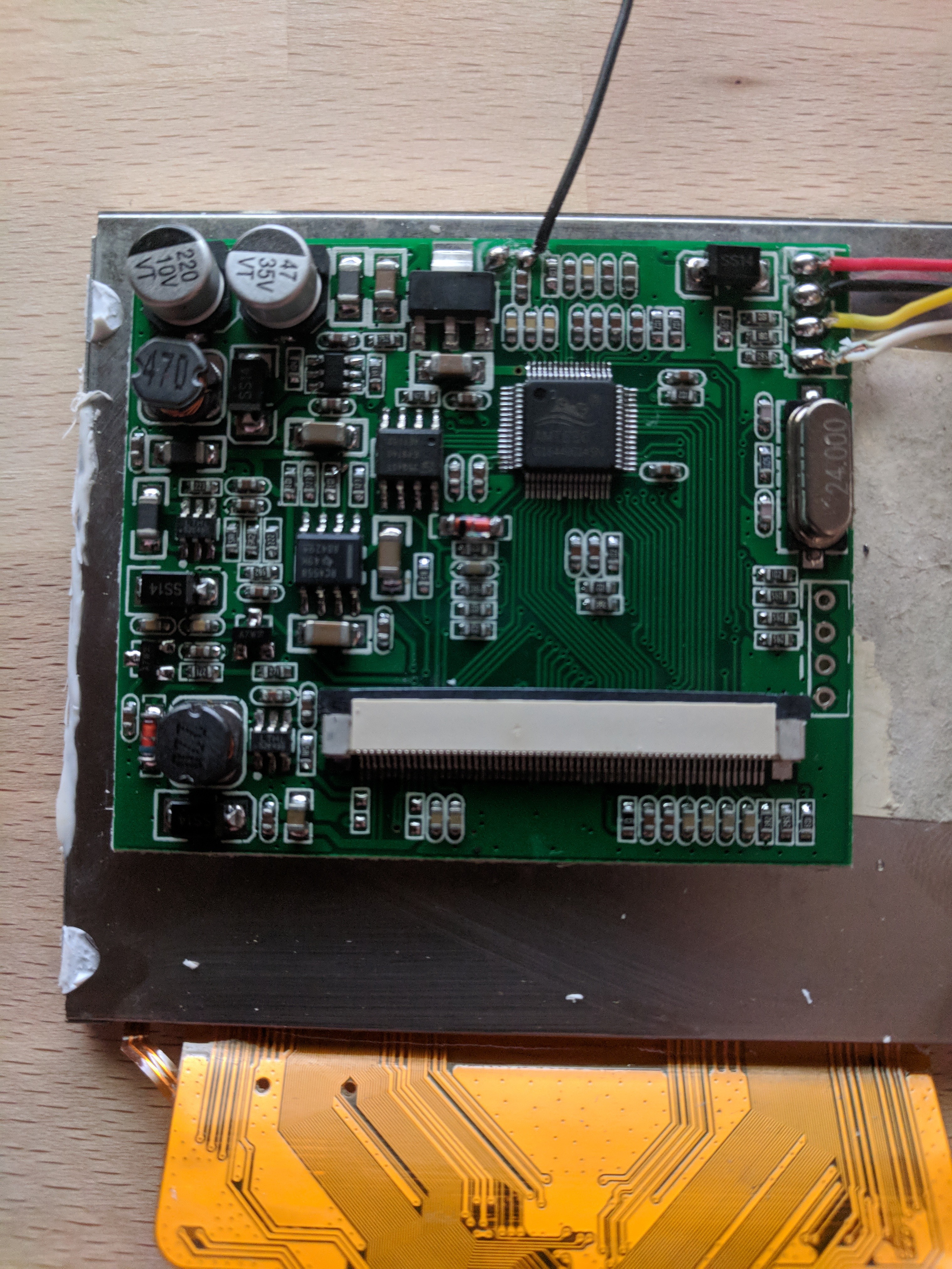
- IMG_20180402_183350~2.jpg (2.71 MiB) Viewed 6165 times
Also, the red wire near the top, for the buttons, got disconnected. I figure it isn't a big deal.
Re: Help with BW screen
Posted: Tue Apr 03, 2018 12:20 pm
by Hex
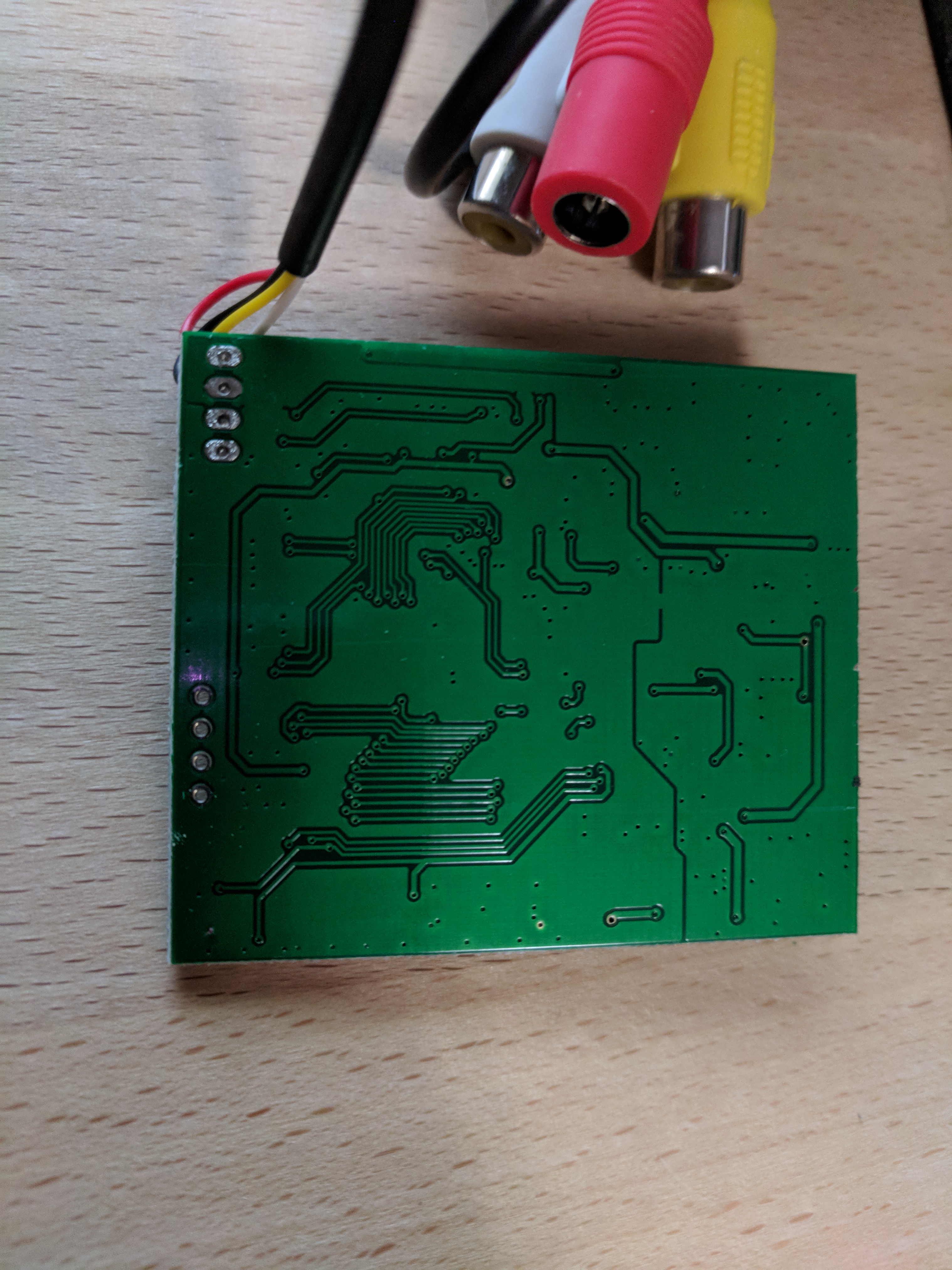
Can you remove the board from the lcd and show me the bottom of the PCB?
Re: Help with BW screen
Posted: Tue Apr 03, 2018 3:48 pm
by Nealon
Hex wrote: ↑Tue Apr 03, 2018 12:20 pm
Can you remove the board from the lcd and show me the bottom of the PCB?
Like this?
- IMG_20180403_174306.jpg (3.2 MiB) Viewed 6130 times
Re: Help with BW screen
Posted: Fri Apr 06, 2018 10:47 pm
by Ashaka
I have the same board. Has any progress been made?
Re: Help with BW screen
Posted: Sat Apr 07, 2018 11:51 pm
by Nealon
I'm waiting on a hub to come so I can connect a keyboard to my pi, since i may or may not have to change a line in a config file so the pi will output to the display instead of hdmi. I'm going to test it first by connecting a usb head to the red and black wires and see if it will work with 5v without modding anything. If that doesn't work I'm going to make a guess and see if the mod for variant 8 works. I'll share how it goes.
Re: Help with BW screen
Posted: Mon Apr 09, 2018 1:39 pm
by Hex
Hey Nealon Can you read the markings on the IC besides the broken Red wire on the button pcb ? That is most likely 3.3v regulator
If it is then you can just connect the Pi's 3.3v to it and you would not need anything else to mod
Re: Help with BW screen
Posted: Mon Apr 09, 2018 2:21 pm
by Nealon
It is marked 1117h on the top line, and then 33 1w7b on the bottom line.
Re: Help with BW screen
Posted: Mon Apr 09, 2018 6:23 pm
by Hex
1117h is a linear voltage regulator so you are in luck. If you can try connecting 3.3v from pi to the middle pin (output pin) then you have a working display. no need of 5v hack
Have a look at page 3 > SOT223
https://www.ece.usu.edu/ece_store/spec/LM1117T.pdf
Re: Help with BW screen
Posted: Tue Apr 10, 2018 9:07 am
by nwycoff37
Hex wrote: ↑Mon Apr 09, 2018 6:23 pm
1117h is a linear voltage regulator so you are in luck. If you can try connecting 3.3v from pi to the middle pin (output pin) then you have a working display. no need of 5v hack
Have a look at page 3 > SOT223
https://www.ece.usu.edu/ece_store/spec/LM1117T.pdf
Any tips of how you would go about soldering this connection from the middle pin to the pi? the pin is so tiny and its very close to another small electrical component. Im pretty new to soldering so I appreciate any advice.
Thanks
-Nick
Re: Help with BW screen
Posted: Tue Apr 10, 2018 12:05 pm
by Hex
The tab sticking out upwards is also connected to middle pin. You can use that to connect to pi's 3.3v pin