Page 1 of 3
BW 3.5 TFT LCD - 5V modification
Posted: Sun Oct 07, 2018 8:56 am
by schnauzbart
Hi all,
I just started my first try on a GameBoy Zero.
Therefore i purchased this 3.5 inch tft lcd display from BW:
(
https://www.amazon.de/KFZ-R%C3%BCckfahr ... op?ie=UTF8)
My problem here is, that the board doesn't fit any I found online.
It's similar to a Variant 2 but not really the same.
https://www.sudomod.com/wiki/index.php/GBZ_Screen

- board
- 20181007_1634208.jpg (2.7 MiB) Viewed 7286 times
I've connected the display to 12V and 5V and measured out the voltage values on the chip, I suppose, is the DC/DC-converter.
In most guides the DC/DC-Converter is skipped by just connecting 5V to the VOUT pin.
My version however only has 4V output. I'm afraid that I will damage the board by connecting 5V to the pin I measured 4V.
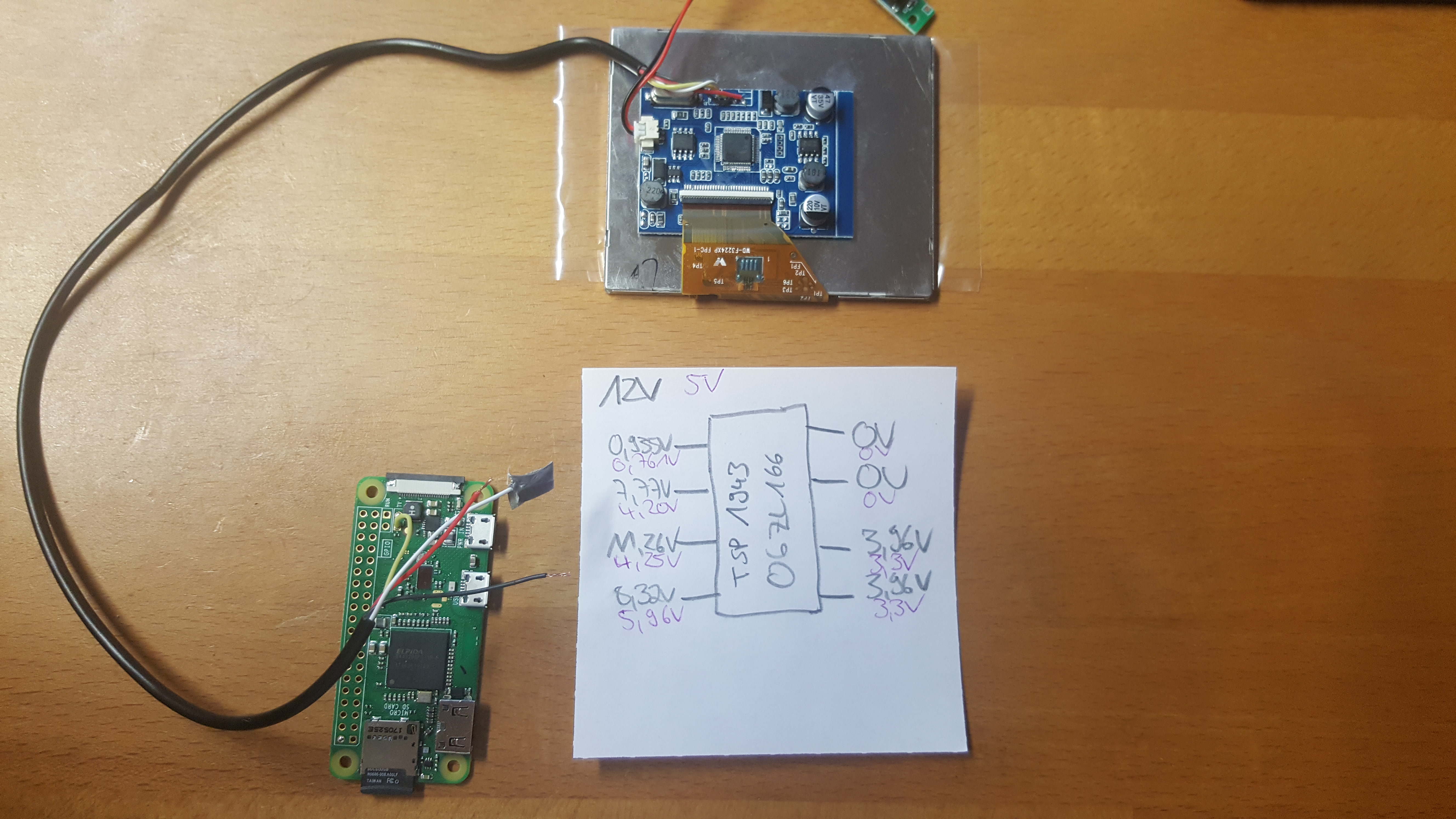
- values
- 20181007_163409.jpg (3.64 MiB) Viewed 7286 times
If anyboy is able to help me I would be really glad.
Thank you for your answers!
Greetings
schnauzbartS
Re: BW 3.5 TFT LCD - 5V modification
Posted: Tue Nov 27, 2018 8:32 am
by Basil Ruys
Hi,
I have the same issue.
Screen arrived today, opened it and the board didn't mach with any of the ones in the guides.
I used the ling from variant 1 to amazon.co.uk.
If anyone could share there methodes of how they found out where to solder, that may be a start...
Re: BW 3.5 TFT LCD - 5V modification
Posted: Fri Nov 30, 2018 4:34 pm
by Zhuraj
Hi,
I got the same bw screen today. It seems that this is the new model. Has someone success in powering these with 5v ?
Re: BW 3.5 TFT LCD - 5V modification
Posted: Sat Dec 01, 2018 5:24 am
by McGyver
What you measure on the chip output could be some rest of AC ripple. Try to measure on the big capacitor on the picture bottom. There you should get something closure to 5V. You can inject your 5V as well on this cap. Take care: if you measure something close to 3.3V DO NOT inject 5V there!
Re: BW 3.5 TFT LCD - 5V modification
Posted: Sat Dec 01, 2018 5:39 am
by Zhuraj
Hi mcgiver,
Thanks for your Reply. Im a Newby with this. But i will Try this today and give Feedback. I have just one question left: with wich voltage do i have to test this? I guess i must try this with 12v and when i get 5v on the cap i must solder the output to the plus on the board and Switch to 5v input with(hopefully) nice picture in the screen whitout flickering correct?
Thanks again!
EDIT: Ive quickly checked this.with 12v input there are 4.01V on the cap output. Dont know if this a good or bad value. I will wait for an answer till i Continue.
Re: BW 3.5 TFT LCD - 5V modification
Posted: Sat Dec 01, 2018 6:09 am
by McGyver
How do you measure: where do you touch your ground port from the measurement device to the display PCB? Because 4V is a bit strange...
Re: BW 3.5 TFT LCD - 5V modification
Posted: Sat Dec 01, 2018 6:20 am
by Zhuraj
Hi,
Ive put the ground on the board ground.was this wrong?
I measure anywhere on the board either 12v or 4v. It looks to me as if this board runs with 4v. Is that possible? If so, can the screen operate with the 5v from Rasperry?
Re: BW 3.5 TFT LCD - 5V modification
Posted: Tue Dec 04, 2018 10:24 am
by Le Nerdarto
im at the same point on this project with the same screen and board right now....
if I make any progress i will report...
if someone gets it running on 5v, help would be appreciated

Re: BW 3.5 TFT LCD - 5V modification
Posted: Tue Dec 04, 2018 1:53 pm
by brainslugs83
Sometimes voltage drops if there is load on the line -- I wouldn't be surprised if the 4v you're measuring is really 5v, but there is a load on it (e.g. it's driving the screen, so it drops a volt). -- You could try running the screen directly off of 5v -- and if it's dim, try temporarily bridging to one of the 4v spots and seeing if it gets bright (e.g. with an alligator clip or something).
Note 1: if it doesn't fix the dimness issue, disconnect it immediately, those are not the traces you're looking for!
Note 2: Beware, that could totally let the magic smoke out of the device, especially if you're not careful, so do it at your own risk...
Note 3: the little 8-pin DIL chip (two components above the big tin can cap that you're probing) looks a lot like the voltage regulator from some of the mod guides -- I would probe some of those pins to see if any of those are 5v... / there's also that 35v filter cap above (probably just a buffer for the input voltage, but it's worth probing).
Re: BW 3.5 TFT LCD - 5V modification
Posted: Mon Dec 10, 2018 8:47 am
by Basil Ruys
I did try to run it on 5v, but the backlight just goes on and of the whole time.
No picture shows up either...