Page 1 of 2
Screen problem
Posted: Wed Jan 09, 2019 10:57 am
by Paxe87
Hi guys, I have a question for you
I just received my display unfortunately I have no idea how to convert it 12V to 5V
is very similar to those from the guide, however, it is not the same

Re: Screen problem
Posted: Wed Jan 09, 2019 4:43 pm
by tinkerBOY
If your board has the XL1509 chip responsible for converting the 12v input to 5v then read my
GearBest Screen 5v mod post.
Re: Screen problem
Posted: Thu Jan 10, 2019 12:35 am
by Paxe87
Thank you,
I read and look easy, but I did not find these components on my board. I have those
Re: Screen problem
Posted: Fri Jan 11, 2019 10:01 am
by rodocop
You could just google those numbers and find some data sheets on those chips. Also, if you have a 12V power source and a multi-meter. Power the screen with 12V and probe those chips and find a spot where 5V is being output, and connect your 5V power there.
Re: Screen problem
Posted: Sat Jan 12, 2019 8:21 pm
by tinkerBOY
rodocop wrote: ↑Fri Jan 11, 2019 10:01 am
You could just google those numbers and find some data sheets on those chips. Also, if you have a 12V power source and a multi-meter. Power the screen with 12V and probe those chips and find a spot where 5V is being output, and connect your 5V power there.
This is exactly how I do the 5v mod to any 12V screen for Game Boy Zero. These screens use different dc regulators but they're all basically the same. They take 12v input and convert that to 5v.
Re: Screen problem
Posted: Sun Jan 13, 2019 7:23 am
by infinitLoop
I got a few of these too since they were running on special on amazon. The pin you want is pin 2 on the 2013s chip.
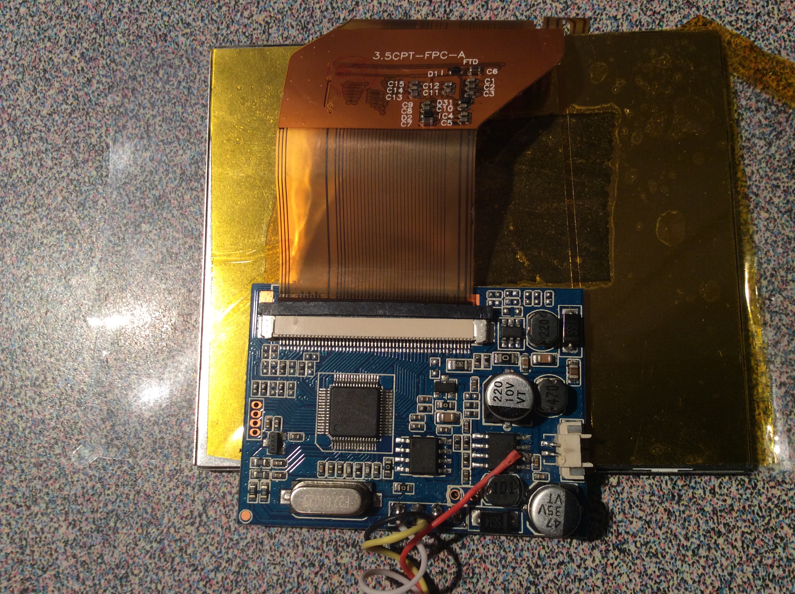
- 993FFDDA-C63F-493B-B2A2-19B84EDDBB99.jpeg (2.06 MiB) Viewed 4794 times
Re: Screen problem
Posted: Sun Jan 13, 2019 7:43 am
by infinitLoop
Btw. Nice photos... it took me quite a few tries in zooming and angling to try and get my phone’s camera to read the writing on the chips. Once I did that, I googled around with those various numbers till I found the schematics for 2013s which looked pretty promising, with 5v on it. Multimeter tests seemed to agree when I had it powered through the standard 12v in. I’ve wired up three like that and they worked like gangbusters.
Re: Screen problem
Posted: Sun Jan 13, 2019 8:40 pm
by tinkerBOY
For anyone with the same screen, the schematics is at
http://img009.hc360.cn/m8/M07/AA/BB/wKh ... jTI860.pdf.
Connect your 5v directly to the RZC2013S' pin 3.
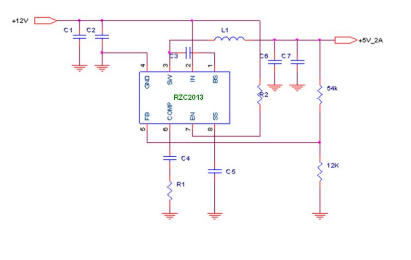
- rzc2013s.PNG (148.9 KiB) Viewed 4770 times
Re: Screen problem
Posted: Tue Jan 15, 2019 5:19 am
by Paxe87
infinitLoop wrote: ↑Sun Jan 13, 2019 7:43 am
Btw. Nice photos... it took me quite a few tries in zooming and angling to try and get my phone’s camera to read the writing on the chips. Once I did that, I googled around with those various numbers till I found the schematics for 2013s which looked pretty promising, with 5v on it. Multimeter tests seemed to agree when I had it powered through the standard 12v in. I’ve wired up three like that and they worked like gangbusters.
Thanks,
I took pictures of this little helper
Re: Screen problem
Posted: Tue Jan 15, 2019 5:45 am
by infinitLoop
did this work with pin 2 because that is the 12v in, and the pin 3 is the 5v out? so pin 2 works the same as if you just use the input pad?