Page 1 of 1
Screen Issue - white wire? Yellow wire? Both?
Posted: Mon Jan 21, 2019 10:46 pm
by DoubleO7
Hi, this is my second Gameboy zero build (the first was the adafruit kit but really like the actual Gameboy housing with silicone pad buttons vs tactile switches. Anyway, a little confused on wiring the screen to pi zero. I have the backup screen and found the correct board to change to 5v. On weren't original build he has the yellow and white wires both connected to pi zero (white to the video in out and looks like the yellow going to the ground pad directly next to it). On a forum on here it shows to use either the white or yellow to the video input pad and ground (black wire) to the pad next to it. Could someone provide a better understanding of which to do. Sorry if this is a newbie question ! Thanks!!+
Re: Screen Issue - white wire? Yellow wire? Both?
Posted: Tue Jan 22, 2019 2:37 am
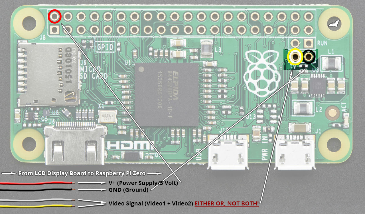
by tinkerBOY
Re: Screen Issue - white wire? Yellow wire? Both?
Posted: Tue Jan 22, 2019 7:09 am
by rodocop
tinkerboys diagram is good. But also, in wermy's original guide, he did just ground one of the signal wires (like you mentioned). I typically use yellow, and just get rid of the white wire completely. For your references, yellow and white are usually AV1 and AV2.
I typically wire this way (with the exception that I connect 5v to the power supply, not the pi).
Re: Screen Issue - white wire? Yellow wire? Both?
Posted: Tue Jan 22, 2019 7:22 pm
by DoubleO7
Thanks Tinkerboy! I did as you suggested (connecting the white and black) on my screen board and the "fuzziness" ( was not getting good screen resolution - interference ) issue is resolved! Much appreciated guys for the feedback!