New Screen Variation

Having trouble with your GBZ build? Ask your questions here!
BrownBoard
Posts: 1
Joined: Sun Mar 03, 2019 11:59 am

New Screen Variation

Post by BrownBoard » Sun Mar 03, 2019 12:40 pm

I'm working on my first GBZ project and I got my screen in today. I bought the recommended Amazon screen. BW brand. However I can't find the variation on the Wiki. I even checked the numbers on the chip and I don't see anything similar. PLEASE SEND HELP!
screen-1w.jpg
screen-1w.jpg (2.25 MiB) Viewed 9129 times
I think I need to do the 5v mod on one of these two chips.
screen-2w.jpg
screen-2w.jpg (909.92 KiB) Viewed 9129 times
RZC2013S
X283A1
screen-3w.jpg
screen-3w.jpg (1022.84 KiB) Viewed 9129 times
P25D40H
8J1EC1D

User avatar
correia5022
Posts: 202
Joined: Mon Dec 05, 2016 12:32 am
Location: Portugal
Has thanked: 17 times
Been thanked: 38 times

Re: New Screen Variation

Post by correia5022 » Mon Mar 04, 2019 1:48 pm

PIN3 on the RZC2013S
SW
Power Switching Output. SW is the switching node that supplies
power to the output. Connect the output LC filter from SW to the
output load.

So wire vcc to pin3 (3rd on the bottom from left to right on your picture)
________________________________________
Starting on electronics :)
My first build, 2 years later
https://sudomod.com/forum/viewtopic.php ... 8&start=30
Check out my Boombox: https://nrcboombox.wixsite.com/website

lasercatz
Posts: 8
Joined: Sun Feb 17, 2019 6:22 am
Location: Maine
Has thanked: 4 times
Been thanked: 3 times
Contact:

Re: New Screen Variation

Post by lasercatz » Tue Mar 05, 2019 2:46 pm

I have the same version. Desolder the power (red) from where it is and resolder onto that chip, as correia5022 said. It will work, but be careful since it is such a small area to solder. also, once it's on there really nail it down with hot glue, otherwise it can twist around and pull off the pad (see my post above "Toasted driver board") Major sad face.

3kidsinaustin
Posts: 27
Joined: Sat Dec 29, 2018 8:21 pm
Been thanked: 7 times

Re: New Screen Variation

Post by 3kidsinaustin » Wed Mar 06, 2019 3:19 pm

Here is a picture to help. I don't think you need to remove the chip. I was having some issues that I believe ended up being improper grounding, but had removed the chip by then.
20190102_075224.jpg
20190102_075224.jpg (2.67 MiB) Viewed 9045 times
First Build Done! viewtopic.php?f=43&t=7444

g-raffballs
Posts: 4
Joined: Tue Jun 18, 2019 8:54 am
Has thanked: 2 times

Re: New Screen Variation

Post by g-raffballs » Mon Jul 29, 2019 1:10 pm

Yo guys and Girls,
I have the same screen and an odd thing happens:
If I bridge the Chip like it's explained in the Wiki, the monitor doesn't turn on at all. It even stops the whole Gameboy (pi & controller PCB) from powering up!
And now comes the clue, if I Power up and then apply the bridge (temporarily by hand) it works like a charm!
I'm not a geek in electronics...sooo WHAT THE HECK is happening?!
Any tips?

manyxcxi
Posts: 17
Joined: Sat Mar 02, 2019 12:22 pm
Location: Portland, OR, USA
Has thanked: 6 times
Been thanked: 6 times
Contact:

Re: New Screen Variation

Post by manyxcxi » Wed Oct 30, 2019 10:36 am

g-raffballs wrote:
Mon Jul 29, 2019 1:10 pm
... an odd thing happens:
If I bridge the Chip like it's explained in the Wiki, the monitor doesn't turn on at all. It even stops the whole Gameboy (pi & controller PCB) from powering up!
And now comes the clue, if I Power up and then apply the bridge (temporarily by hand) it works like a charm!
I'm not a geek in electronics...sooo WHAT THE HECK is happening?!
Any tips?
I was having a similar issue, I was checking bad grounds, a weak power supply, everything and would still have the issue. I finally desoldered the chip and bridged pin 3 to VCC and it worked like a charm.

jesuscrist
Posts: 4
Joined: Sun Dec 29, 2019 11:08 pm
Has thanked: 10 times

Re: New Screen Variation

Post by jesuscrist » Mon Dec 30, 2019 3:42 pm

I have the same type of screen and the board is the same as yours, on pin 2 of the voltage regulator you have to bridge with the power that comes from the red wire and it is all you need to do to make it work properly.
SpoilerShow
Image

zentrum104
Posts: 5
Joined: Mon Dec 23, 2019 2:35 pm
Been thanked: 1 time

Re: New Screen Variation

Post by zentrum104 » Sat Jan 04, 2020 3:52 am

Actually, I would recommend to perform the 5V mod by soldering to the inductor pad, as shown in my picture:
IMG_20200104_112833.jpg
IMG_20200104_112833.jpg (2.41 MiB) Viewed 7982 times
Reason:
SpoilerShow
The inductor is in series with pin 3 of the IC an therefore creates a high impedance on the power supply line of the screen. Depending on the rest of your power network, that could cause unstable power supply for the screen. In my case the picture was flickering and the screen regularly shut down. Now it works like a charm ;)
RZC2013.PNG
RZC2013.PNG (202.78 KiB) Viewed 7982 times
You can also find a datasheet to the step-down converter here: http://img009.hc360.cn/m8/M07/AA/BB/wKh ... jTI860.pdf

R A V I O L I
Posts: 2
Joined: Wed Apr 29, 2020 9:19 pm
Been thanked: 1 time

Re: New Screen Variation

Post by R A V I O L I » Fri May 08, 2020 10:41 pm

zentrum104 wrote:
Sat Jan 04, 2020 3:52 am
Actually, I would recommend to perform the 5V mod by soldering to the inductor pad, as shown in my picture:

IMG_20200104_112833.jpg

Reason:
SpoilerShow
The inductor is in series with pin 3 of the IC an therefore creates a high impedance on the power supply line of the screen. Depending on the rest of your power network, that could cause unstable power supply for the screen. In my case the picture was flickering and the screen regularly shut down. Now it works like a charm ;)
RZC2013.PNG
You can also find a datasheet to the step-down converter here: http://img009.hc360.cn/m8/M07/AA/BB/wKh ... jTI860.pdf
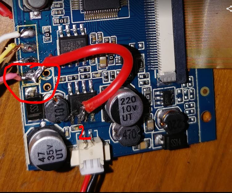
how did you remove the coil that was there

Ryman08
Posts: 1
Joined: Sat Jan 07, 2017 7:41 pm

Re: New Screen Variation

Post by Ryman08 » Wed Jan 12, 2022 8:18 pm

I got this one from Amazon and struggled to get a clean picture even with a shielded video wire. I ended up pulling out the chip and that coil mentioned in a previous comment and soldered directly to the coil pad. Once I did that the picture cleaned up and I didn't have anymore issues.

To remove the coil I attempted to heat the solder by contacting the pad underneath, but in doing so I accidently pulled the coil off except for the wires and the base of it. Once I cut off the wires I was able to slowly heat up and remove the base (through loosening with the heat and further breaking of the base). Once I got enough space to heat up the rest of the solder, the entire pad cleaned up and I was able to solder to it.

Post Reply

Who is online

Users browsing this forum: No registered users and 1 guest