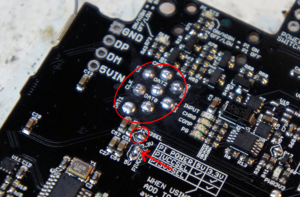
Hi. Yesterday I started my YaGPi3v1 and soldered the Pi3ext to the board. I found with a continuity tester a connection between GND and GPIO10 (between the black painted ones) on the board. I then desoldered the two pins and sucked them off. I can slide kapton tape between so it's separated from the Pi3ext. The connection is on the side of the board.
Is this a known defect on a few boards? Or is the board guaranteed to be ok and I soldered a connection? I soldered with very little solder. Or should there be a connection?
[Solved] - [V0.6C1] Connection between GND and GPIO10 on the board
- moooarcuuuus
- Posts: 232
- Joined: Tue Jul 04, 2017 1:28 am
- Has thanked: 2 times
- Been thanked: 94 times
[Solved] - [V0.6C1] Connection between GND and GPIO10 on the board
Last edited by moooarcuuuus on Sun Jan 21, 2018 11:31 pm, edited 1 time in total.
Eat, Sleep, Eat, Sleep, Eat, Sleep, Eat, Sleep, Eat, Sleep, Eat, Sleep, Eat, Sleep, Eat, Sleep, Eat, Sleep, Eat, Sleep, Eat, Sleep, Eat, Sleep, Eat, Sleep, Eat, Sleep, Eat, Sleep, Eat, Sleep, Eat, Sleep, Eat, Sleep, Eat, Sleep, Eat, Sleep, Eat, Sleep, Eat, Sleep, Eat, Sleep, Eat, Sleep, Eat, Sleep, Eat, Sleep, Eat, Sleep, Eat, Sleep, Eat, Sleep, Eat, Sleep, Eat, Sleep, Eat, Sleep, Eat, Sleep... Game Over
- kite
- Posts: 972
- Joined: Thu May 12, 2016 4:30 am
- Location: UK
- Has thanked: 246 times
- Been thanked: 361 times
- Contact:
Re: [V0.6C1] Connection between GND and GPIO10 on the board
Hi, what issues are you having with it when running?
GPIO10 is G0, which is the least significant bit of green. To be honest if this one is grounded you would hardly notice the difference!
The pin BELOW it (GPIO10 is the one at the TOP of your pictures) .. is meant to be GND.
The pi3ext doesn't have common ground, or at least the version you have probably doesn't .. it literally just extends the one pin, so that pin being GND is fine

Stock clearance - CLOSED: viewtopic.php?f=38&t=12064
Kite's Mailing List: https://goo.gl/forms/e97uUvPOfUxPWdz82
Kite's FAQ: https://kiteretro.com/faq/


Kite's Mailing List: https://goo.gl/forms/e97uUvPOfUxPWdz82
Kite's FAQ: https://kiteretro.com/faq/


- moooarcuuuus
- Posts: 232
- Joined: Tue Jul 04, 2017 1:28 am
- Has thanked: 2 times
- Been thanked: 94 times
Re: [V0.6C1] Connection between GND and GPIO10 on the board
I haven't tested it yet. I'll do it this evening.
Eat, Sleep, Eat, Sleep, Eat, Sleep, Eat, Sleep, Eat, Sleep, Eat, Sleep, Eat, Sleep, Eat, Sleep, Eat, Sleep, Eat, Sleep, Eat, Sleep, Eat, Sleep, Eat, Sleep, Eat, Sleep, Eat, Sleep, Eat, Sleep, Eat, Sleep, Eat, Sleep, Eat, Sleep, Eat, Sleep, Eat, Sleep, Eat, Sleep, Eat, Sleep, Eat, Sleep, Eat, Sleep, Eat, Sleep, Eat, Sleep, Eat, Sleep, Eat, Sleep, Eat, Sleep, Eat, Sleep, Eat, Sleep, Eat, Sleep... Game Over
- moooarcuuuus
- Posts: 232
- Joined: Tue Jul 04, 2017 1:28 am
- Has thanked: 2 times
- Been thanked: 94 times
Re: [V0.6C1] Connection between GND and GPIO10 on the board
I soldered the two pins again. The display works. Is the color curve ok? I havent connected the USB yet, so the arduino, audio and hub should switch later to ON, right?
On the Pi is an older part of the extension (without the extra 5V and GND connectors). I think it is ok to use it, right?
On your wiki are two 3,3V bridges. On my board is only one. I only close the 3,3V and dont close the 5V bridge. Is it right?
https://raw.githubusercontent.com/geebl ... PTER/6.jpg
For what is the 5V bridge?
Eat, Sleep, Eat, Sleep, Eat, Sleep, Eat, Sleep, Eat, Sleep, Eat, Sleep, Eat, Sleep, Eat, Sleep, Eat, Sleep, Eat, Sleep, Eat, Sleep, Eat, Sleep, Eat, Sleep, Eat, Sleep, Eat, Sleep, Eat, Sleep, Eat, Sleep, Eat, Sleep, Eat, Sleep, Eat, Sleep, Eat, Sleep, Eat, Sleep, Eat, Sleep, Eat, Sleep, Eat, Sleep, Eat, Sleep, Eat, Sleep, Eat, Sleep, Eat, Sleep, Eat, Sleep, Eat, Sleep, Eat, Sleep, Eat, Sleep... Game Over
- kite
- Posts: 972
- Joined: Thu May 12, 2016 4:30 am
- Location: UK
- Has thanked: 246 times
- Been thanked: 361 times
- Contact:
Re: [V0.6C1] Connection between GND and GPIO10 on the board
Colours look good to me
and yes when you hook up USB then the other tests should pass OK.
You only need the 3.3v jumper, so that's all good as you have it. Ignore 5V.
On the pi3 on the RIGHT side there are two solder holes with + and -, it's a good idea to get some silicone wire and solder those up to the corresponding pins on the SAIO:


You only need the 3.3v jumper, so that's all good as you have it. Ignore 5V.
On the pi3 on the RIGHT side there are two solder holes with + and -, it's a good idea to get some silicone wire and solder those up to the corresponding pins on the SAIO:

Stock clearance - CLOSED: viewtopic.php?f=38&t=12064
Kite's Mailing List: https://goo.gl/forms/e97uUvPOfUxPWdz82
Kite's FAQ: https://kiteretro.com/faq/


Kite's Mailing List: https://goo.gl/forms/e97uUvPOfUxPWdz82
Kite's FAQ: https://kiteretro.com/faq/


- moooarcuuuus
- Posts: 232
- Joined: Tue Jul 04, 2017 1:28 am
- Has thanked: 2 times
- Been thanked: 94 times
Re: [V0.6C1] Connection between GND and GPIO10 on the board
On the green marked are 3,3V bridgepads. Is that for the fan? In your wiki, the fan is connected to a connector on the board. Does it care if the fan is connected to the Pi3ext (bridge closed) or on the board?
Eat, Sleep, Eat, Sleep, Eat, Sleep, Eat, Sleep, Eat, Sleep, Eat, Sleep, Eat, Sleep, Eat, Sleep, Eat, Sleep, Eat, Sleep, Eat, Sleep, Eat, Sleep, Eat, Sleep, Eat, Sleep, Eat, Sleep, Eat, Sleep, Eat, Sleep, Eat, Sleep, Eat, Sleep, Eat, Sleep, Eat, Sleep, Eat, Sleep, Eat, Sleep, Eat, Sleep, Eat, Sleep, Eat, Sleep, Eat, Sleep, Eat, Sleep, Eat, Sleep, Eat, Sleep, Eat, Sleep, Eat, Sleep, Eat, Sleep... Game Over
- kite
- Posts: 972
- Joined: Thu May 12, 2016 4:30 am
- Location: UK
- Has thanked: 246 times
- Been thanked: 361 times
- Contact:
Re: [V0.6C1] Connection between GND and GPIO10 on the board
All good questions btw 
The RED that you have highlighted should connect to the 'vcc' that i showed in my previous picture. All this is doing is allowing more current (thicker cable) for GND + VCC (which because we used the '3.3v jumper' means that VCC = 3.3V). The thin FPC can't handle much current so for reliability the extra cable is used.
The green is marked for the FAN. The reason is that I upgraded it because it was really annoying to have so many cables come from the Pi3 itself when not needed ... so solder a fan to the solder holes, and then bridge the fan enable jumper (looks like you have already done it, so all good there)
I should really update those pics to make it clearer!
Stock clearance - CLOSED: viewtopic.php?f=38&t=12064
Kite's Mailing List: https://goo.gl/forms/e97uUvPOfUxPWdz82
Kite's FAQ: https://kiteretro.com/faq/


Kite's Mailing List: https://goo.gl/forms/e97uUvPOfUxPWdz82
Kite's FAQ: https://kiteretro.com/faq/


- moooarcuuuus
- Posts: 232
- Joined: Tue Jul 04, 2017 1:28 am
- Has thanked: 2 times
- Been thanked: 94 times
Re: [V0.6C1] Connection between GND and GPIO10 on the board
Thx 4 info. 

Eat, Sleep, Eat, Sleep, Eat, Sleep, Eat, Sleep, Eat, Sleep, Eat, Sleep, Eat, Sleep, Eat, Sleep, Eat, Sleep, Eat, Sleep, Eat, Sleep, Eat, Sleep, Eat, Sleep, Eat, Sleep, Eat, Sleep, Eat, Sleep, Eat, Sleep, Eat, Sleep, Eat, Sleep, Eat, Sleep, Eat, Sleep, Eat, Sleep, Eat, Sleep, Eat, Sleep, Eat, Sleep, Eat, Sleep, Eat, Sleep, Eat, Sleep, Eat, Sleep, Eat, Sleep, Eat, Sleep, Eat, Sleep, Eat, Sleep... Game Over
Who is online
Users browsing this forum: No registered users and 1 guest