Page 1 of 1
CSL won't boot
Posted: Fri Aug 16, 2019 7:21 pm
by eggbowl
Hello, I have a CSL and as I was putting it together everything was going well, up until i put the sd card. I flashed the image on the sd card with balena, and i used notepad to change the mode to test. I can't get any type of picture on the screen. I've tried multiple sd cards, ones that have worked fine in other rpi0s the backlight for the lcd is on, and all the test leds are lit. i'm pretty confident that it's not the pi because i had tested it before with vanilla retropie and it showed a picture. what could be wrong?
Re: CSL won't boot
Posted: Sat Aug 17, 2019 12:52 am
by kite
Hi,
Electronics look fine, but the Pi isn't booting, meaning the SD card isn't being read correctly. Looking at your pictures, one of those test pads on the Pi itself is missing (ripped off or otherwise). Unfortunately due to the way it was designed, those test pads go through a trace to the SD card.. meaning there is a missing connection to the SD card so it won't boot!
Here is a zoomed in picture of that pad to see what I mean:
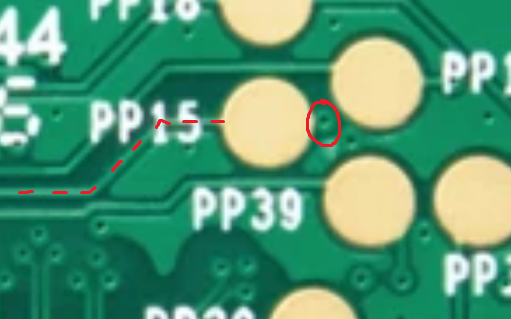
- sd_pin.png (324.47 KiB) Viewed 2288 times
The fix is to solder a small wire to bridge the gap of the missing pad to that little circle (it's called a 'via')
It is possible to repair, I can repair for a price if you email me.
Re: CSL won't boot
Posted: Sat Aug 17, 2019 5:53 pm
by eggbowl
Thanks for response. I was going to use this pi in a different gbz that had a cartridge sd reader like wermys build, but I accidentally ripped off the pad so I decided to use it for this one instead. I didn't know that it was necessary for function. For the bridge, I should use magnet wire right? Will 34 gauge be small enough or do I go lower?
Edit: I know wire gagues are inverted I meant higher number/smaller diameter.
Re: CSL won't boot
Posted: Mon Aug 19, 2019 3:13 am
by kite
Magnet wire would work, the thinnest thing possible because the area to attach solder to is so tiny. You'll need to carefully scrape away the soldermask to reveal the copper. Be careful not to scrape away the neighbouring copper as it will be GND, which when soldered will just short out the pin meaning it won't function


