Page 4 of 5
Re: Dreamcast VMU Pi
Posted: Thu Jul 20, 2017 5:26 pm
by Mirk
Hello all! I now have everything I need to build this. Its been a dream since 99 to have a gameboy inside a vmu. I first tried to do this a year ago by cramming a watch phone inside but I could never get the controls to work. I then saw your youtube vid satri360 and have since been buying what is needed. My problem is I am kinda of a noob at this. Mostly software related. So any help with the code that is needed to get this working would be amazing. I think I have the video figured out but for sound I have no clue. My soldering skills are also not the best. Been practicing your guide abrugsch.
I found this
https://www.youtube.com/watch?v=WpAbeKMVBFE and on their twitter these pics. Really wish I new what screen was used.
- Untitled-2.jpg (140.42 KiB) Viewed 12170 times
- Untitled-3.jpg (157.45 KiB) Viewed 12170 times
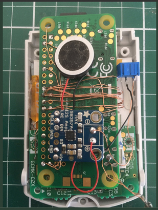
So I bought the sound card from these pics. I have no clue how to do the software but the wiring looks easy enough.
On this
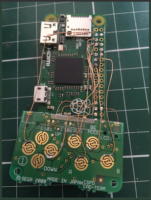
- vmu_pcb_pad_ic1_soldered.png (476.69 KiB) Viewed 12170 times
How did you solder this without it spilling over? can I use something as like dividers? Its so damn small.

And here

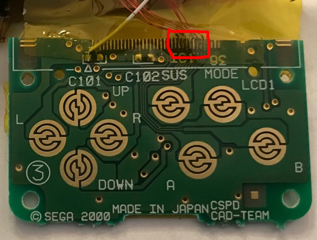
- vmu_oled_pcb_cut.png (520.53 KiB) Viewed 12170 times
Is what I have circled what you mean?
I plan on cutting up and solder some vmus this weekend to try and get the controls done. I have 12 to work with so here's hoping I can do it in 12 tries.

Re: Dreamcast VMU Pi
Posted: Fri Jul 21, 2017 12:23 am
by abrugsch
Mirk wrote: ↑Thu Jul 20, 2017 5:26 pm
How did you solder this without it spilling over? can I use something as like dividers? Its so damn small.
Lots of flux, fine wires and a fine soldering tip...
You can also use the vias (the small holes in the pcb linking traces from one side to the other)
Re: Dreamcast VMU Pi
Posted: Fri Jul 21, 2017 1:57 am
by moosepr
if this is your first project you really are jumping in at the deep end!!!!
The screen is actually an adafruit one
https://www.adafruit.com/product/1431 the yellow box is showing how much of the pcb he left remaining, and the red dots show some of the places he attached wires
Re: Dreamcast VMU Pi
Posted: Fri Jul 21, 2017 4:38 am
by Mirk
While not my first project it is definitely the smallest. I did pick up that lcd to follow satri360 guide but pomegd got back to me and link me the screen he used.
http://www.aitendo.com/product/11455
Its a 1.8 screen with 128x160 rez so I assume in software he change the rotation and position of the display. I plan on using the oled on the first build. For the controls I am going to attempt to solder a few vmu boards using the teeny tiny contacts but if that fails just go for the pads themselves. If time allows this weekend I'll post my progress. Thanks guys!
Re: Dreamcast VMU Pi
Posted: Fri Jul 21, 2017 4:56 pm
by Mirk
I have been giving this a bit of a go tonight and I have hit a few snags. I have trimmed down everything I could and making sure everything will fit. That inductor on the powerboost 500 is indeed to tall. I can not find a way to make it fit. I have tried searching google for a low profile replacement and I am having no luck. The 2 I have found that I think will work the mim order is 2500+. Could one of you fine gents point me in the right direction on where I might find one or a different power charge that would fit better would be great too!

Re: Dreamcast VMU Pi
Posted: Sat Jul 22, 2017 1:15 am
by abrugsch
What value/size is the inductor? I found a low profile wurth one on RS to replace the tall one on my small powerboost equivalent...
See here:
http://www.sudomod.com/forum/viewtopic. ... tor#p33614
Re: Dreamcast VMU Pi
Posted: Sat Jul 22, 2017 2:17 am
by moosepr
Alternatively have a look at my projects. None have power boosts in them. The pi will happily run as low as 3v, so as long as you protect the battery from being over discharged you will be ok. Charging is also a consideration. The charge/protect boards I use are pretty small, or you could just buy a protected cell, and add an extra connector for charging purposes
Re: Dreamcast VMU Pi
Posted: Sun Jul 23, 2017 2:47 pm
by obsidianspider
I managed to sandwich things in with a cheap charge/protect board, but it's not boosting up to 5V. That said, the cheap 128x128 screen I'm using doesn't need it.
Re: Dreamcast VMU Pi
Posted: Mon Jul 24, 2017 2:22 pm
by Mirk
I haven't got much done since I am waiting on a few thing to come in. I think I can make it all fit if I remove the hdmi and mini usb connectors on the pi. I have 4 to use so I can set up the software on another.
Re: Dreamcast VMU Pi
Posted: Tue Sep 05, 2017 8:19 am
by satri360
Mirk wrote: ↑Thu Jul 20, 2017 5:26 pm
I found this
https://www.youtube.com/watch?v=WpAbeKMVBFE and on their twitter these pics. Really wish I new what screen was used.
So I bought the sound card from these pics. I have no clue how to do the software but the wiring looks easy enough.
I am not sure what he is using but assume one of the 1.44" 128x128 ILI9163 just based on the white stiffener of the LCD.
You can follow the complete instruction from the Adafruit to enable the I2S Audio.
https://learn.adafruit.com/adafruit-max ... y-pi-usage
Mirk wrote: ↑Thu Jul 20, 2017 5:26 pm
On this
vmu_pcb_pad_ic1_soldered.png
How did you solder this without it spilling over? can I use something as like dividers? Its so damn small.
I use flux, decent solder iron tips and the Nikon SMZ - stereo microscope. This helps a lot when you solder narrow pitch components like 0.5mm. We might not need this for wiring the VMU I/Os but definitely good for the OLED board. It could a bit pricy to get the best quality of image but an affordable one would be still sufficient for home soldering

.
- Stereomicroscope.jpeg (3.63 KiB) Viewed 11848 times
Mirk wrote: ↑Thu Jul 20, 2017 5:26 pm
And here
vmu_oled_pcb_cut.png
Is what I have circled what you mean?
These spots are marked to attract some attentions when they cut the PCB.
Middle - GND via connecting top and bottom layer. Don't lose it or you have to wire them like I did. Yeah I busted and took me an hour to fix.
Right - VSL (segment voltage reference) via.

- Untitled.png (31.05 KiB) Viewed 11848 times