Pi in a PSP
-
Helder

- Trailblazer

- Posts: 2985
- Joined: Thu May 05, 2016 8:33 am
- Location: Rogers, AR
- Has thanked: 1459 times
- Been thanked: 3114 times
Re: Pi in a PSP
Nice ! Once you have the final pinout I'll route things for you. Now would be a good time to add anything else you want to that large empty board. Any other schematics you plan to add to this?
Chat with me and other members On Discord
Don't contact me about obtaining my board files (as you will not get them). If my Boards or PCB Kits are sold out, they will be restocked as soon as I can get them and there is demand for them. You can join the mailing list on my Website to be notified when they are available.
Helder's Game Tech Website
We will not support any cloned work so don't come to us with technical issues to resolve, go talk to the cloner for help.
-
othermod

- Posts: 43
- Joined: Wed Aug 03, 2016 7:03 pm
- Location: https://t.me/pump_upp
- Has thanked: 6 times
- Been thanked: 21 times
- Contact:
Re: Pi in a PSP
I'm going one of two directions. Either I'm going to add everything to this board, or I'm going to do the bare minimum and shrink the size of it to make manufacturing cheaper.Helder wrote:Nice ! Once you have the final pinout I'll route things for you. Now would be a good time to add anything else you want to that large empty board. Any other schematics you plan to add to this?
I'm adding the audio for sure. I see that one of your boards has audio on it, and I wanted to see how you went about it. The filter I made still has a little bit of static I'd like to remove. I'm at work and none of the site images show up, so I'll have to check it out later today. Also, I'm curious about the power board you mentioned a couple days ago.
-
Helder
- Trailblazer
- Posts: 2985
- Joined: Thu May 05, 2016 8:33 am
- Location: Rogers, AR
- Has thanked: 1459 times
- Been thanked: 3114 times
Re: Pi in a PSP
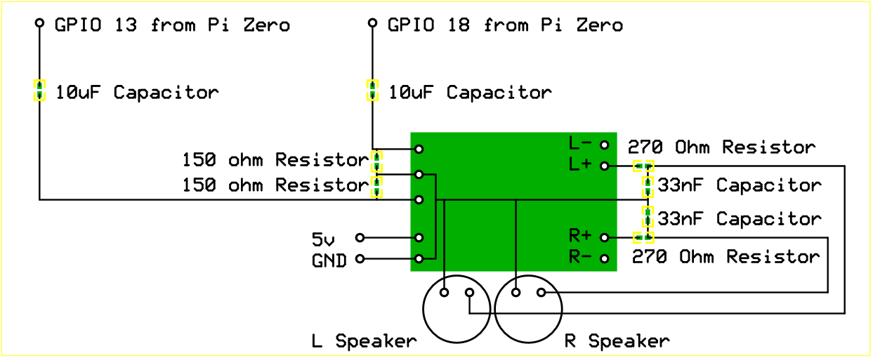
I used the PWM filter then feed it into a potentiometer which then went to the AMP and finally output to a speaker and headphone. The PSP has 2 speakers right? then you can easily add stereo to it if that's the case.othermod wrote: I'm going one of two directions. Either I'm going to add everything to this board, or I'm going to do the bare minimum and shrink the size of it to make manufacturing cheaper.
I'm adding the audio for sure. I see that one of your boards has audio on it, and I wanted to see how you went about it. The filter I made still has a little bit of static I'd like to remove. I'm at work and none of the site images show up, so I'll have to check it out later today. Also, I'm curious about the power board you mentioned a couple days ago.
The power board I have designed (will be here this week for testing) is 2 fold and does what your power board does, it charges the battery at 1A and boosts the 3.7 to 5v at 2A (non switching). It needs testing of course but if all works out then I plan to integrate it into future projects so it is less things to have for a build.
Chat with me and other members On Discord
Don't contact me about obtaining my board files (as you will not get them). If my Boards or PCB Kits are sold out, they will be restocked as soon as I can get them and there is demand for them. You can join the mailing list on my Website to be notified when they are available.
Helder's Game Tech Website
We will not support any cloned work so don't come to us with technical issues to resolve, go talk to the cloner for help.
Don't contact me about obtaining my board files (as you will not get them). If my Boards or PCB Kits are sold out, they will be restocked as soon as I can get them and there is demand for them. You can join the mailing list on my Website to be notified when they are available.
Helder's Game Tech Website
We will not support any cloned work so don't come to us with technical issues to resolve, go talk to the cloner for help.
-
othermod
- Posts: 43
- Joined: Wed Aug 03, 2016 7:03 pm
- Location: https://t.me/pump_upp
- Has thanked: 6 times
- Been thanked: 21 times
- Contact:
Re: Pi in a PSP
Ok so you're using the standard PWM filter from Adafruit's page I'm guessing. I'm doing the same thing and yes the PSP has stereo and works pretty well. I just wish I could get rid of all the hum in the speaker output. Switching to Tantalum capacitors helped a lot, but some noise is still there. I had some luck by putting the high-pass filter before the amp and the low-pass filter after the amp.Helder wrote:I used the PWM filter then feed it into a potentiometer which then went to the AMP and finally output to a speaker and headphone. The PSP has 2 speakers right? then you can easily add stereo to it if that's the case.
The power board I have designed (will be here this week for testing) is 2 fold and does what your power board does, it charges the battery at 1A and boosts the 3.7 to 5v at 2A (non switching). It needs testing of course but if all works out then I plan to integrate it into future projects so it is less things to have for a build.
I'm very curious about your power board (i.e. does it have low battery protection, can your voltage booster be used as an on/off feature in place of a mosfet). I assume you have details posted in one of the topics here, so I'll find it once I'm on an internet connection that isn't limited.
-
johnweland

- Posts: 26
- Joined: Tue May 10, 2016 12:11 pm
- Has thanked: 3 times
- Been thanked: 8 times
- Contact:
Re: Pi in a PSP
As an end user looking to build this I'd say an all in one board, drop it in a 3D printed case plug in the Pi and be on my way. But that's because I don't have much stuff to solder with and get everything assembled, I can only do light soldering with my setup.
-
Helder
- Trailblazer
- Posts: 2985
- Joined: Thu May 05, 2016 8:33 am
- Location: Rogers, AR
- Has thanked: 1459 times
- Been thanked: 3114 times
Re: Pi in a PSP
I've used ceramic 10uf caps and the remedy of the hum seems to be to use some ferrite beads in line with the output audio both the positive and negative. I have 16,000 of these beads (overkill I know but it was at a great deal), if we work on this together then I can throw you some beads for testing this out (send me a PM with your shipping info).othermod wrote:Ok so you're using the standard PWM filter from Adafruit's page I'm guessing. I'm doing the same thing and yes the PSP has stereo and works pretty well. I just wish I could get rid of all the hum in the speaker output. Switching to Tantalum capacitors helped a lot, but some noise is still there. I had some luck by putting the high-pass filter before the amp and the low-pass filter after the amp.Helder wrote:I used the PWM filter then feed it into a potentiometer which then went to the AMP and finally output to a speaker and headphone. The PSP has 2 speakers right? then you can easily add stereo to it if that's the case.
The power board I have designed (will be here this week for testing) is 2 fold and does what your power board does, it charges the battery at 1A and boosts the 3.7 to 5v at 2A (non switching). It needs testing of course but if all works out then I plan to integrate it into future projects so it is less things to have for a build.
I'm very curious about your power board (i.e. does it have low battery protection, can your voltage booster be used as an on/off feature in place of a mosfet). I assume you have details posted in one of the topics here, so I'll find it once I'm on an internet connection that isn't limited.
The board or rather boards I should say are 2 separate parts of one board in the end. One charges the battery and does have battery protection but is always good to use a protected cell anyways. The boost board has an enable pin like the powerboost so it can be set to go off with a mosfet like the Graceful Shutdown that alot of people here are working on. @Camble has found a great smd variant that works well so the space needed for this is small.
Once I get a few soldered up I can send to you for your own tests and maybe it can be integrated into this project.
Chat with me and other members On Discord
Don't contact me about obtaining my board files (as you will not get them). If my Boards or PCB Kits are sold out, they will be restocked as soon as I can get them and there is demand for them. You can join the mailing list on my Website to be notified when they are available.
Helder's Game Tech Website
We will not support any cloned work so don't come to us with technical issues to resolve, go talk to the cloner for help.
Don't contact me about obtaining my board files (as you will not get them). If my Boards or PCB Kits are sold out, they will be restocked as soon as I can get them and there is demand for them. You can join the mailing list on my Website to be notified when they are available.
Helder's Game Tech Website
We will not support any cloned work so don't come to us with technical issues to resolve, go talk to the cloner for help.
-
othermod
- Posts: 43
- Joined: Wed Aug 03, 2016 7:03 pm
- Location: https://t.me/pump_upp
- Has thanked: 6 times
- Been thanked: 21 times
- Contact:
Re: Pi in a PSP
Have you seen my on/off circuit? I'm pretty sure he got the TXD sensing idea from my siteHelder wrote: I've used ceramic 10uf caps and the remedy of the hum seems to be to use some ferrite beads in line with the output audio both the positive and negative. I have 16,000 of these beads (overkill I know but it was at a great deal), if we work on this together then I can throw you some beads for testing this out (send me a PM with your shipping info).
The board or rather boards I should say are 2 separate parts of one board in the end. One charges the battery and does have battery protection but is always good to use a protected cell anyways. The boost board has an enable pin like the powerboost so it can be set to go off with a mosfet like the Graceful Shutdown that alot of people here are working on. @Camble has found a great smd variant that works well so the space needed for this is small.
Once I get a few soldered up I can send to you for your own tests and maybe it can be integrated into this project.
http://www.sudomod.com/forum/viewtopic. ... 092#p12092
On mine, the same momentary button that powers everything on also issues the shutdown command when pressed. The only thing I don't have is emergency shutdown, and that's only because I'm against using a second switch. I intend to make a long press cause a forced shutdown.
http://othermod.com/raspberry-pi-soft-onoff-circuit/
Sweet Jesus that's a lot of ferrite beads. I'm happy to test anything and I'lll send a PM later today.
-
Helder
- Trailblazer
- Posts: 2985
- Joined: Thu May 05, 2016 8:33 am
- Location: Rogers, AR
- Has thanked: 1459 times
- Been thanked: 3114 times
Re: Pi in a PSP
I have seen your image and wasn't sure where people got their info but the question I have is will that work with that BangGood power supply I saw you used in your original build? Many people on here use this power supply and if there is an easy way (with a board made) to shut it off that would be great to have.othermod wrote: Have you seen my on/off circuit? I'm pretty sure he got the TXD sensing idea from my site. Some people referenced my site a while back and Camble was involved in the conversation
http://www.sudomod.com/forum/viewtopic. ... 092#p12092
On mine, the same momentary button that powers everything on also issues the shutdown command when pressed. The only thing I don't have is emergency shutdown, and that's only because I'm against using a second switch. I intend to make a long press cause a forced shutdown.
http://othermod.com/raspberry-pi-soft-onoff-circuit/
Sweet Jesus that's a lot of ferrite beads. I'm happy to test anything and I'lll send a PM later today.
Maybe you could give me some more info on this shutdown circuit since you seem to be the originator.
Chat with me and other members On Discord
Don't contact me about obtaining my board files (as you will not get them). If my Boards or PCB Kits are sold out, they will be restocked as soon as I can get them and there is demand for them. You can join the mailing list on my Website to be notified when they are available.
Helder's Game Tech Website
We will not support any cloned work so don't come to us with technical issues to resolve, go talk to the cloner for help.
Don't contact me about obtaining my board files (as you will not get them). If my Boards or PCB Kits are sold out, they will be restocked as soon as I can get them and there is demand for them. You can join the mailing list on my Website to be notified when they are available.
Helder's Game Tech Website
We will not support any cloned work so don't come to us with technical issues to resolve, go talk to the cloner for help.
-
othermod
- Posts: 43
- Joined: Wed Aug 03, 2016 7:03 pm
- Location: https://t.me/pump_upp
- Has thanked: 6 times
- Been thanked: 21 times
- Contact:
Re: Pi in a PSP
This will work with any power supply. The whole thing acts like a switch on the +5v.Helder wrote: I have seen your image and wasn't sure where people got their info but the question I have is will that work with that BangGood power supply I saw you used in your original build? Many people on here use this power supply and if there is an easy way (with a board made) to shut it off that would be great to have.
Maybe you could give me some more info on this shutdown circuit since you seem to be the originator.
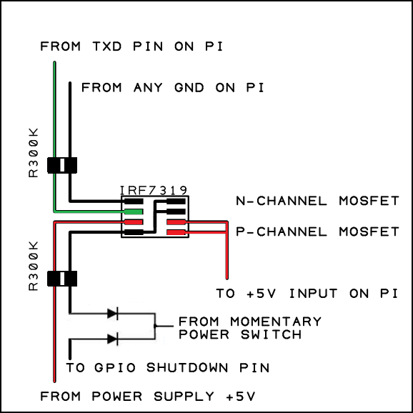
What happens is when you press and hold the power button, it connects the P-mosfet gate to ground and allows power to show through and to the Pi. The Pi now begins to power on. After about a second the OS starts booting and pulls the TXD pin high. The TXD is connected to the gate of the N-mosfet and the output of the N-mosfet is connected to the gate of the P mosfet, so when the N-mosfet is switched on by the TXD, it also serves to permanently keep the P-mosfet on and keeps the Pi powered.
When the OS shuts down the TXD switches to low, which kills the N-mosfet, which then kills the P-mosfet and totally kills power to the Pi.
This is very simple to make into a board. Its just an 8-pin chip and 2 resistors. Also, if you want the same button to turn the Pi off, just put a BAT54C dual diode on the switch wire and connect one end to a GPIO pin and the other to the P-mosfet gate. Then just use software to look for the voltage drop when the button is pressed. And there you have it, soft on/off.
-
Camble

- Posts: 885
- Joined: Thu May 05, 2016 2:31 am
- Location: Scotland
- Has thanked: 269 times
- Been thanked: 488 times
Re: Pi in a PSP
@othermod I originally borrowed the UART pin idea from @Popcorn but we decided using a BCM pin was stable in half the time during boot up.
The schematic I've designed to go with the banggood supply is essentially the same as your dual MOSFET setup.
The schematic I've designed to go with the banggood supply is essentially the same as your dual MOSFET setup.
Who is online
Users browsing this forum: No registered users and 1 guest