I know, I know – “MORE mintyPi stuff??” Other projects coming soon I promise. 🙂
Helder’s newest parts have started shipping out, and so have orders for the latest updates to the 3d-printed parts, so I wanted to put together a sort of supplemental guide to show you what you need to know about the new parts. Hoolyhoo and I have also been hard at work on some significant updates to the pre-made RetroPie image for the mintyPi, so I wanted to cover all that as well.
Before I get into that though, another forum member (dryja123) is doing another mintyPi giveaway! There are a couple ways to enter, and one of them is for a good cause so please check it out: http://sudomod.com/forum/viewtopic.php?f=38&t=4334
New logo designed by CJ Weatherford: https://www.instagram.com/weatherfordcj16/
Parts list for this remains basically the same (if you order parts from Helder or I then you’ll be getting the latest parts), and can be found here: http://www.sudomod.com/wiki/index.php?title=MintyPi
I added the silicone sheet shown in the video (and talked about below) to the parts list as well.
If you’re a video guide kind of person, be sure to watch both the updated/supplemental guide above as well as the previous one. The updated guide has links to timestamps within the previous video for the parts I skipped over (it didn’t make much sense to do an exhaustive guide all over again). If you’re a written guide kind of person, be sure to read the previous written guide along with this — I’ll just be covering the differences here.
The Tin
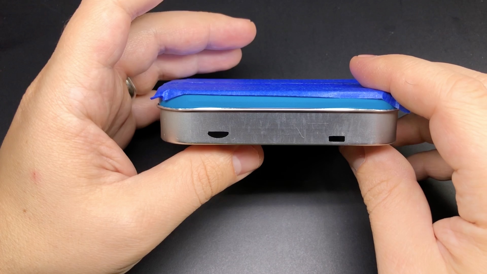
The only real difference with the tin this time around is the placement of the micro USB charging port: it’s moved in a little from last time to make room for the new position of the USB sound card. This time the center of it needs to be about 23.5mm in from the side of the tin. I’ve also updated the drill guide to reflect this.
The 3D-Printed Parts
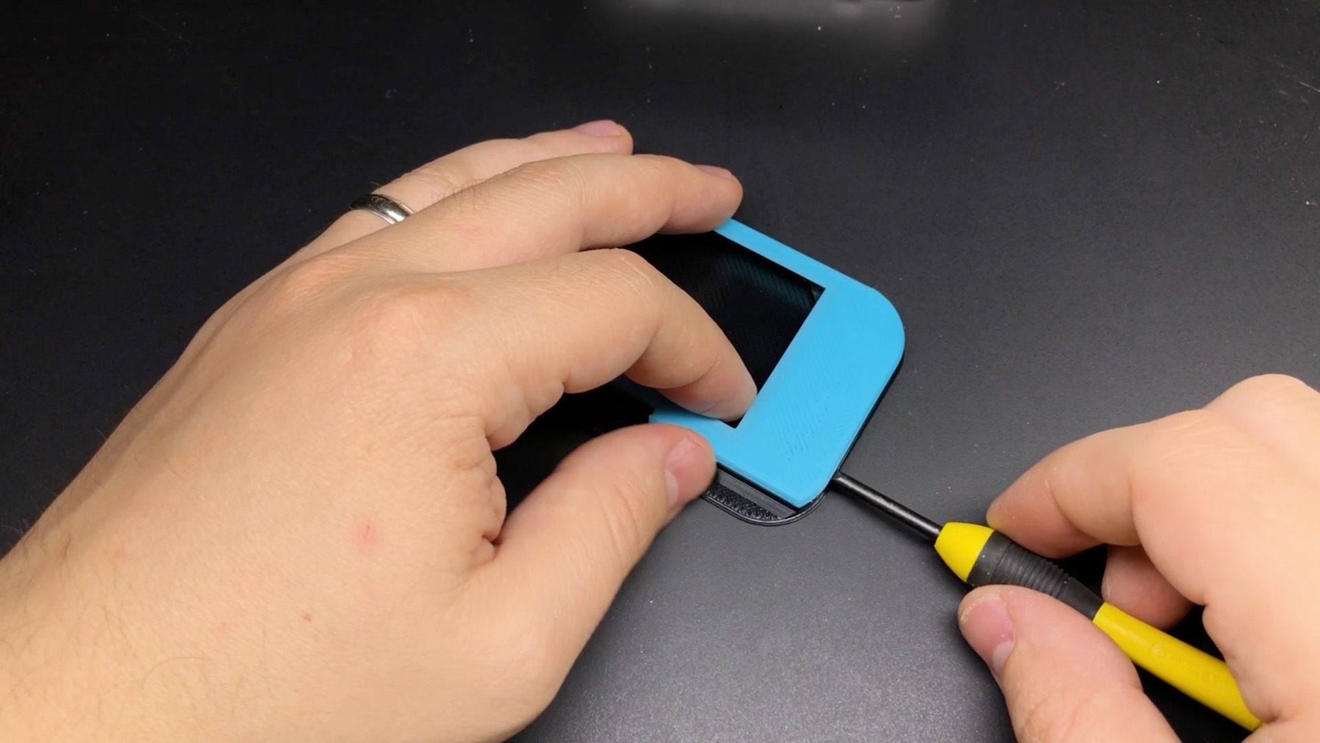
The biggest visible change with this update is that the bezels no longer require screws; they snap into place with 6 pegs and holes (STL files linked to on the wiki, under FAQs: http://www.sudomod.com/wiki/index.php?title=MintyPi#FAQ ). The tolerances can be really tough to get right on those, and can even vary between prints. I’ve added some notches cut out from the edges of the screen backplate so that you should be able to use something flat like a screw driver to (CAREFULLY) pry the bezel off should you need to, but it the bezel will probably fit pretty tight the first time you insert it. So what I recommend is inserting it once before putting anything together, then gently (again, CAREFULLY) prying it back off. This should loosen it up just enough so it’s not ridiculously tight the next time you put it on or remove it. Hopefully you put the bezel on and never need to remove it, though (and with the updated screen parts from Helder with the pre-soldered screen, there’s a good chance that will be the case). I’ve started test-fitting each set that I send out to make sure they fit well.
The other big change is to the baseplate in the bottom of the tin. The USB sound card is now positioned next to where the charging board goes. The cutout in the bottom of the base plate is intended to line up with the chip on the underside of the sound card. Repositioning it here keeps us from having to remove the crystal. Woo hoo!

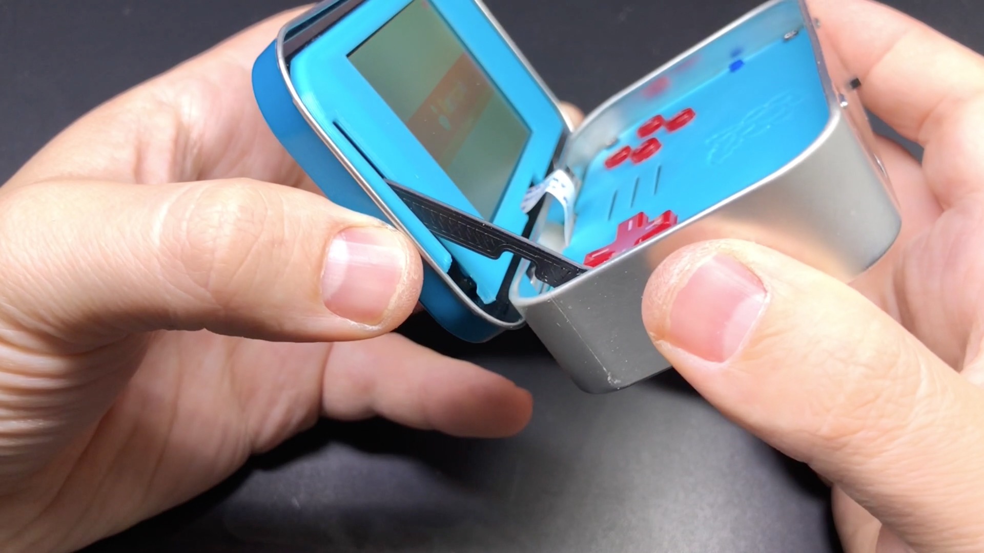
Something thing that happened to me this time around that’s worth pointing out: make sure you don’t position your screen backplate too far towards the back of the tin. If you do that then the bottom-left corner of the bezel may catch on the lower part of the tin as you open it. If this happens to you, you may be able to fix it by taking a file to that corner of the bezel and smoothing it out a bit.
The PCB
NOTE: Be careful not to touch the metal pads on the screen PCB board while it is powered on! Your fingers can provide enough conductivity to essentially bridge them and cause problems (or potentially damage it). You can easily prevent this by putting a piece of tape over those pads. A forum thread with more information can be found here. Thanks to forum member dryja123 for pointing this out!
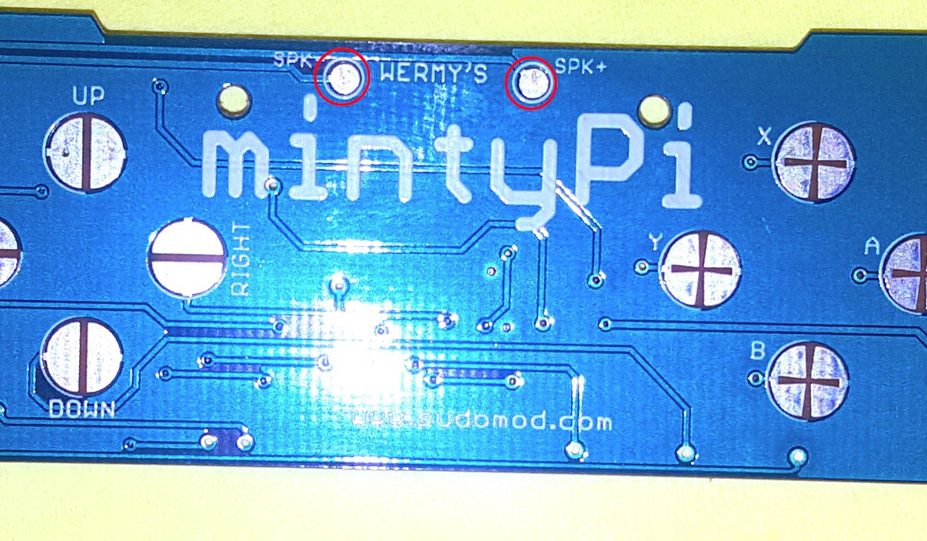
As I mentioned in a previous video/post, this latest version of Helder’s PCB has built-in battery monitor circuitry. But something that wasn’t mentioned before: now there are a couple extra pads added to make wiring your speaker easier. There are two pads on the top side for you to wire your speaker directly to:
Then there are a couple of pads on the underside for you to connect your sound card to (the pads on the sound card that your speaker would have been connected to in the previous guide). This is just a convenience to keep you from having to route those wires all over so it will be cleaner and easier to close up.
The Function Button
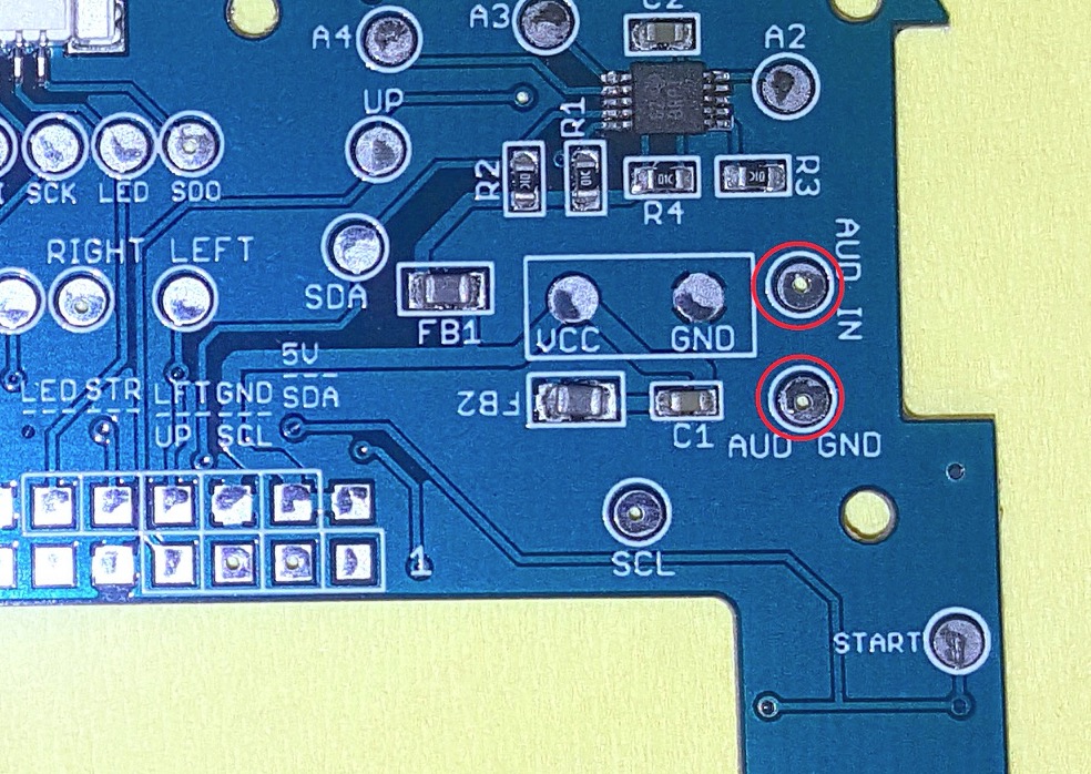
As I showed in a previous video/post, the latest PCBs have a couple pads on the bottom for you to connect a button to. Previously this was just for shutting down the system safely on-demand from anywhere. It does a lot more than that now (more on that later). Adding this button is optional (it can be configured to be start if you prefer – again, more on that later), but it’s highly recommended – it makes it much more convenient. You can add the button pretty much anywhere that it will fit. I’ve seen people add it on the front of the tin, the side, even the back. My preference is to drill a hole about 3.5mm in diameter, 3.25mm in from the edge opposite of the start/select buttons. If you do this, then a 6mm tall tactile switch fits nicely (and you can find them in a variety of colors). This also positions it right next to the pads on the PCB for the button. Handy!
Then you can just use a couple of dabs of glue to hold it in place.
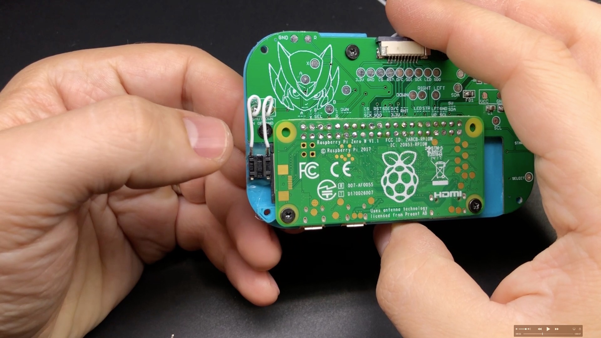
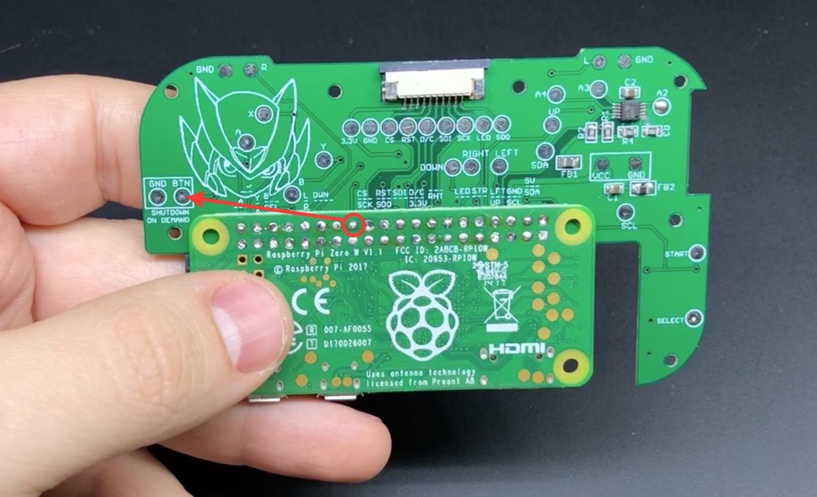
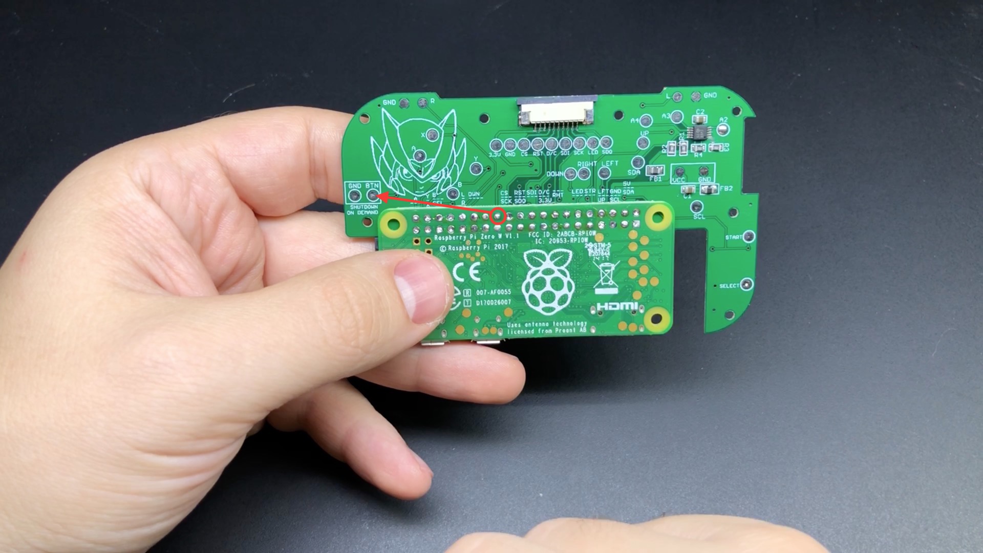
You can test continuity between the pinhole to the left of the CS pin on the PCB, and the button pad, to make sure you’ve got a good connection when you attach your pi.
If you’ve already put your mintyPi together and don’t want to take it apart to add another button, don’t worry: you can change the behavior easily so that another button will trigger the shortcuts. When you set up your SD card, before putting it in your Pi, open /boot/mintyPi/pinfile.txt. It should say 7 by default (because it watches GPIO pin 7). If you change that to say 15, then the start button will act as the function button. This is less than ideal because the start button will bring up a start menu in a game, or a menu in emulationstation (i.e it’s generating a keyboard keystroke), but it does work and will keep you from having to add another hole to your already-built mintyPi.
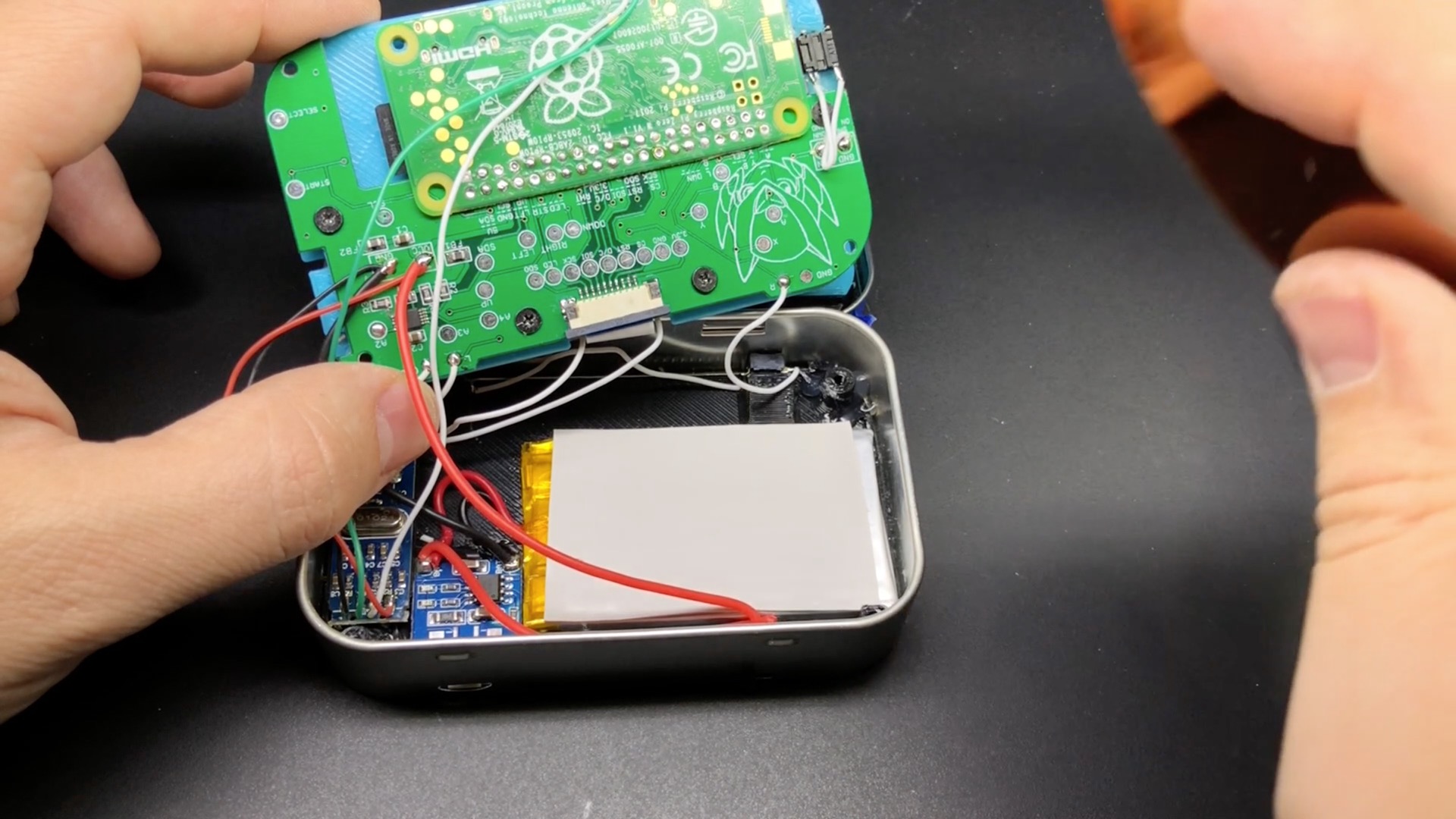
Power Components
Really the only difference between wiring up the power components this time is that the cheaper battery charger we’re using only has one set of BAT+ and BAT- pads, so you wind up having to share. I have the battery connected to those pads (duh), as well as a second set of wires: the positive (red) wire goes to a switch (and then on to the button PCB’s VCC pad), and the ground (black) wire will go to the button PCB. The sound card will share the VCC/GND pads on the button PCB, just so we’re not trying to cram 3 sets of wires on that one set of pads on the charger. Basically the same as last time, though!

One extra precaution I took this time, though, was adding a square of silicone thermal padding on the battery to separate it from the Pi. We enabled overclocking by default in the latest RetroPie image, which does cause the Pi to generate more heat than it did before. Adding this silicone pad will separate the pi and the battery, and should also help diffuse the heat on the back of the pi, so it isn’t all concentrated at one point behind the CPU. Batteries scare me so I like to be extra careful. 🙂 The silicone pad I used is linked to in the parts list on the wiki (link up top).
If the above concerns you, you can turn off overclocking by opening /boot/config.txt and removing these lines (be sure to not remove the itc_arm=on line below them):
arm_freq=1000
gpu_freq=500
core_freq=500
sdram_freq=500
sdram_schmoo=0x02000020
over_voltage=2
sdram_over_voltage=2
Software Update
And that’s about it as far as hardware differences! Now let’s talk about the software updates. The pre-made image is now based off of Retropie 4.3, which gives us a few nice features out of the box like recently-played games list, favorite games list, and updated emulators. We’ve added a couple other big features though – the biggest being a crazy-handy set of shortcuts! Now you can hold the function button (previously the safe-shutdown button) and do the following:
Function + A = Toggle Battery
Function + Y = Toggle Wifi with Icon
Function + B = Toggle Bluetooth with Icon
Function + X = Initiate Safe Shutdown
Function + Dpad Right = Volume Up with Icon
Function + Dpad Left = Volume Down with Icon
Function + Dpad Up = Screen brightness Up
Function + Dpad Down = Screen brightness Down
Function + Right Shoulder = Display Shortcut Cheatsheet
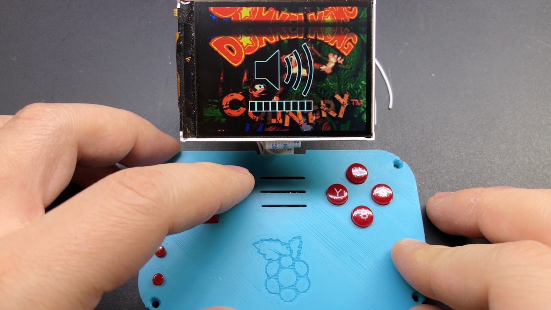
Handy, right?! Also, did you notice the screen brightness shortcuts? With the latest screen/PCB combo from Helder, and using Hoolyhoo’s scripts, you can turn the brightness up and down from anywhere. Pretty awesome!
Another feature I added, if you go in the RetroPie menu, you’ll see an option for “Update mintyPi”. If you select this while connected to wifi, then it will first reach out and update itself (so we can add updates to the update script… hah), and then it will run. It will pull in updates to any customized themes (which is now a customized Material theme by default), pull in updates to Hoolyhoo’s scripts, and any other fixes/tweaks that we find we need later on down the road. This should be very handy in the future, since it will let us add features and/or fixes without you having to open up your mintyPi and remove the SD card.

Other updates to this image include:
• Fixed issue with black screen when no sound card is present
• Included custom mintyPi/sudomod theme from Will.I.Am (pictured below — you can follow him on instagram at @invader_meh). Thanks, Will!
• Tweaked retroarch config so quick save/load now works with select + L/R again
• Updated splash video

The new image is linked to on the wiki (so it only needs to be updated in one spot): http://www.sudomod.com/wiki/index.php?title=MintyPi#Software
I think that about covers it! Huge thanks to Helder for the updated parts, Hoolyhoo for all his work on the scripts included in this update, and Will.I.Am for the custom theme.
Stay tuned for more projects soon!