I had a bunch of people ask for this (sorry it took so long!), so here it is: How to make your own Lamp Zapper!
This is a fun, quick project that could you could probable do in a weekend. When you’re done, you’ll be able to turn on/off a lamp or other small device using an NES Zapper gun!

Here are the parts I used:
For the Zapper:
- An NES Zapper gun (I used an original one. There are knockoffs but I’m not sure what they look like on the inside. All we’re using is the trigger though, really).
- An ATmega328P-based Arduino clone
- Pretty much any Arduino board will do, all we need is a PWM pin. I used this particular board because they come in packs of 5 for $16 on amazon. This particular one doesn’t have a USB interface — you’ll need an FTDI cable (that one should work, though mine is a different brand) to program it. If you don’t expect to do a lot of projects in the future it might be cheaper to just spend a few extra bucks on a board that has USB (this one should work) and save having to get the FTDI cable.
- A 350mAh Li-Po battery from Adafruit (you could probably fit a 500mAh in there pretty easy but this is all I had on hand)
- An Adafruit Micro Lipo battery charging board
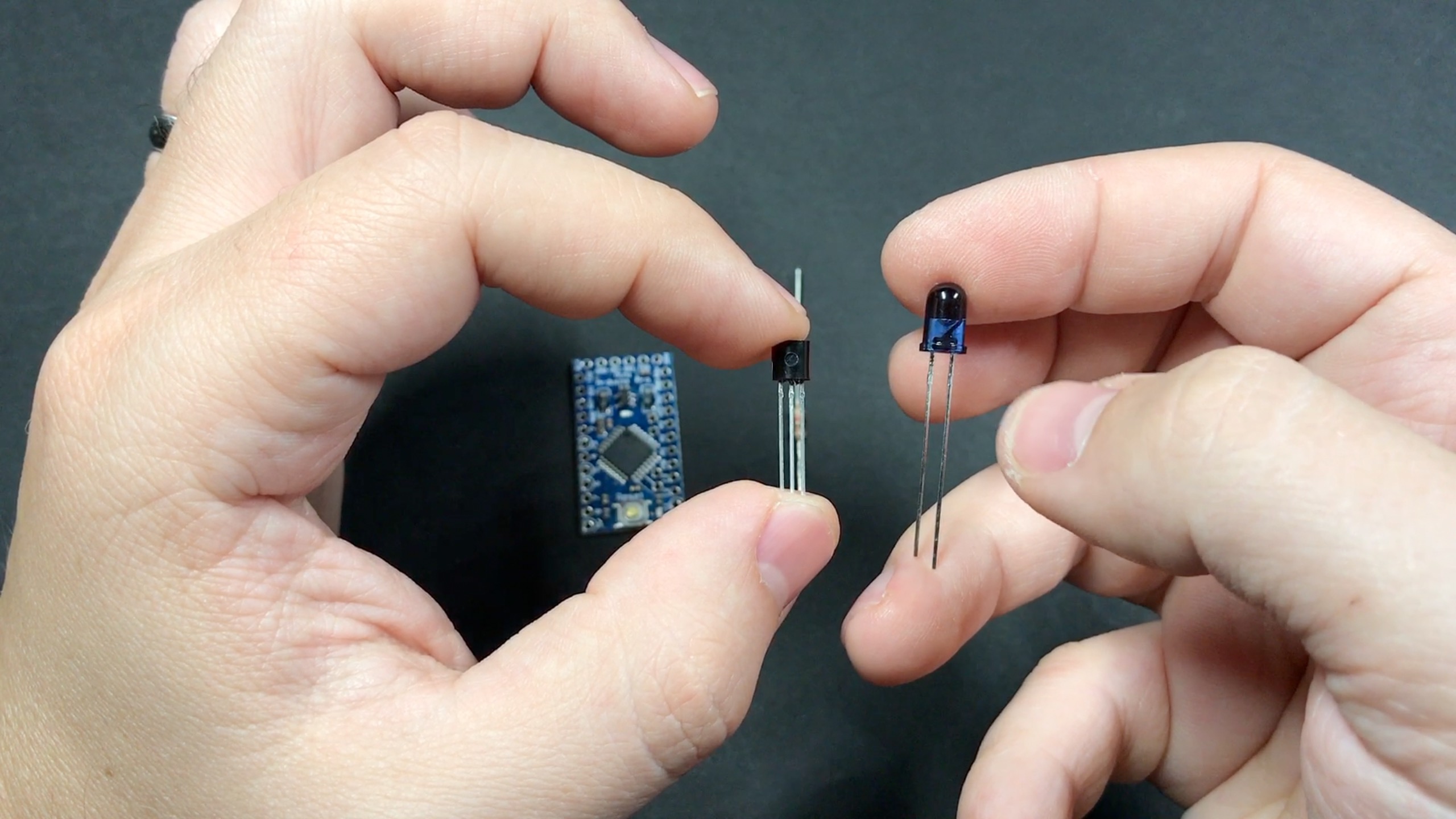
- A “Super-bright” 5mm IR LED
- A 1kOhm resistor
- An NPN transistor (2N2222)
- A power switch (pretty much any small one will do – watch the video for a good look at the one I used)
- A 3D-Printed board for mounting the Arduino board (optional — you could make your own out of some plastic scraps or whatever, but this is nice and clean)
For the Receiver:
- A second ATmega328P Arduino board
- An IR Receiver (TSOP38238)
- A relay (this one is rated for 10A at 125VAC)
- A project box (the one I got is 15cm x 9cm x 5.5cm, you could probably get away with a little thinner)
- Two extension cords: one for bringing power into the box for the Arduino and lamp, and another for the lamp – check out the video or further down in this guide to see what I mean)
- A USB power supply (I used a tiny spare one from an iPhone)
- A spare USB cord for the power supply to power the Arduino (the longer the better)
- A button, which we’ll mount on the side to manually trigger the relay
- Perler beads
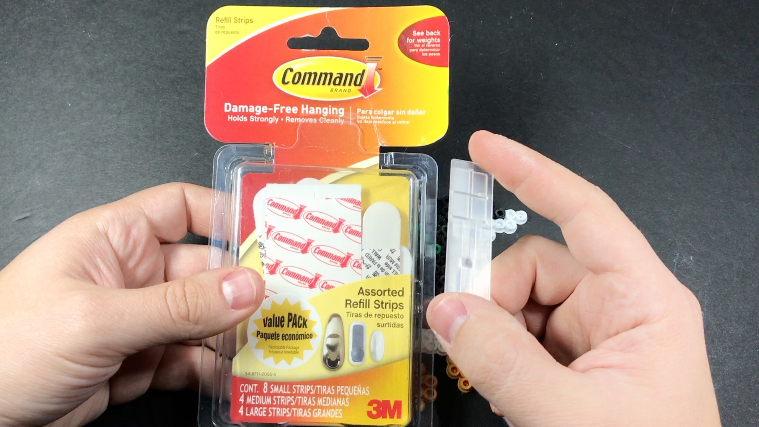
- Command Strips/Hooks
Misc:
- Wire
- Heat-shrink tubing
- Electrical tape
- A drinking straw (you’ll see why!)
Yes, I used several parts from Adafruit, and yes they are a little more expensive. But they are awesome! Consistent quality and great customer service (and no I’m not being paid to say that). You can find equivalent parts on Amazon/ebay if you go looking, though.
The Zapper
If you’re using the same board I did (without a USB connector), go ahead and solder on the header pins so you can program it with the FTDI cable.
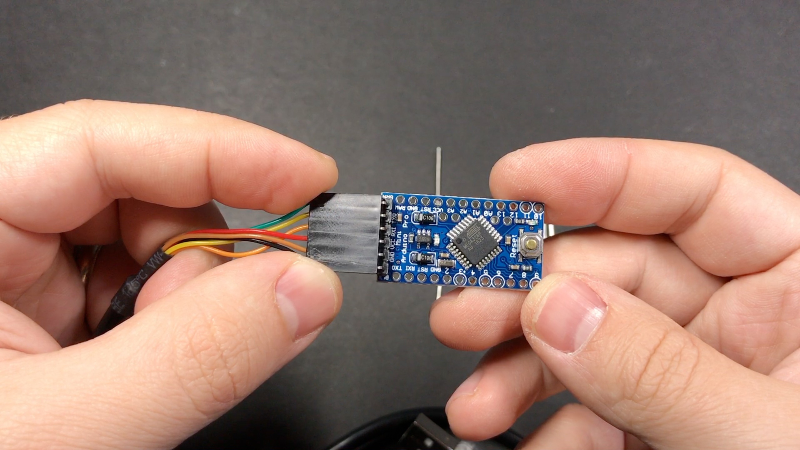
Download this zip file, which contains two Arduino sketches (one for the zapper and one for the receiver), and program the zapper sketch to this board in the Arduino IDE. On mine it was a little tricky to get the timing right: I had to hit the upload button in the IDE and then immediately press the reset button on the Arduino.
This is how I have my IDE configured for this particular board: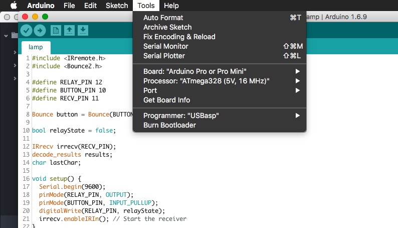
You’ll also need to make sure you have the IRremote and Bounce2 libraries installed – you can do this by going to Sketch -> Include Library -> Manage Libraries and searching/installing them through the IDE.
The way it works is the zapper sketch sends the characters “ZP” whenever you pull the trigger. The receiver watches for those characters, and flips the state of the relay when it sees them.
Now connect a couple wires to the bottom to power it (one to ground and one to VCC), nice and long so they can run from the barrel down into the grip. It’s nicer to do it on the bottom so you can still access the header pins should you want to re-program it in the future.

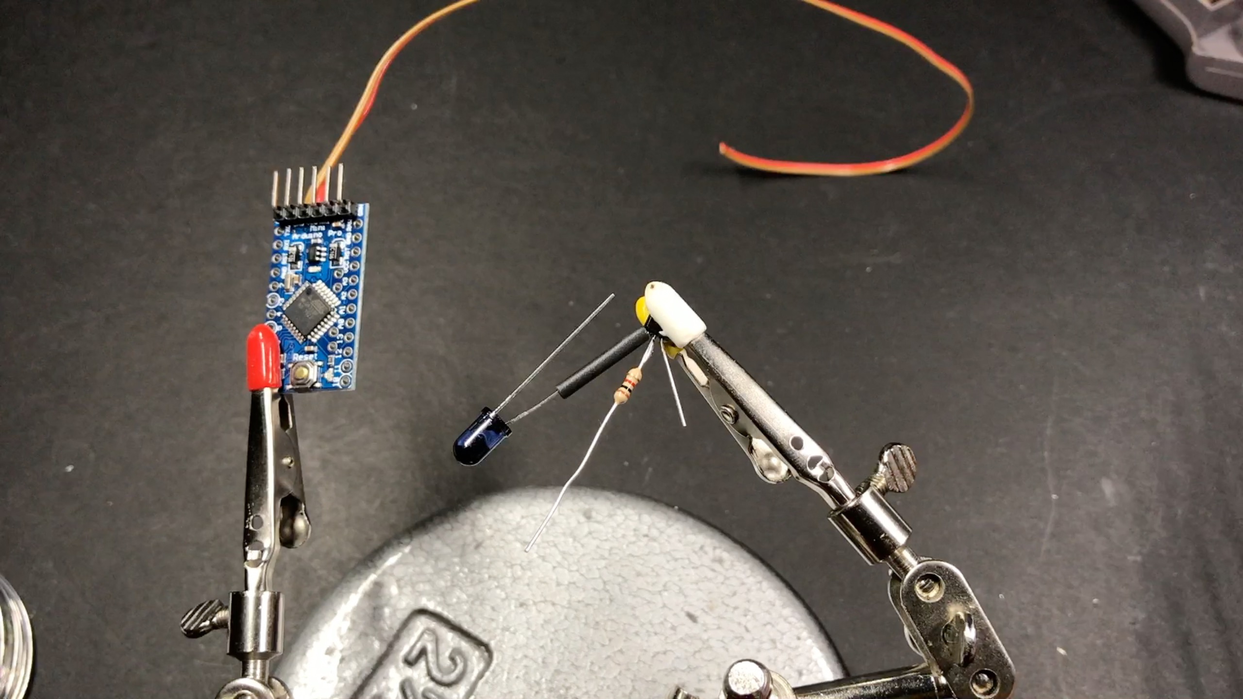
Now we’ll connect the transistor, resistor and LED to the board. You might wonder why we need the transistor. If we were to connect the LED directly to the output pins of the Arduino, it would work, but not very well; the I/O pins on the Arduino just don’t supply enough power. So in stead we’ll hook up a transistor to the output pin, which will then switch on/off power to the LED (which will be connected to one of the VCC pins on the Arduino).
If you’re holding the transistor as shown below, the left pin is ground, the middle pin will be connected to one end of the resistor (the other end of the resistor will be connected to the PWM pin on the Arduino – pin 3 in my case. You may need to update the sketch and use a different pin if you use a different Arduino board), and the right pin will go to the ground pin on the LED (the left/shorter leg below is ground). The positive pin on the LED will go to one of the VCC pins on the Arduino.
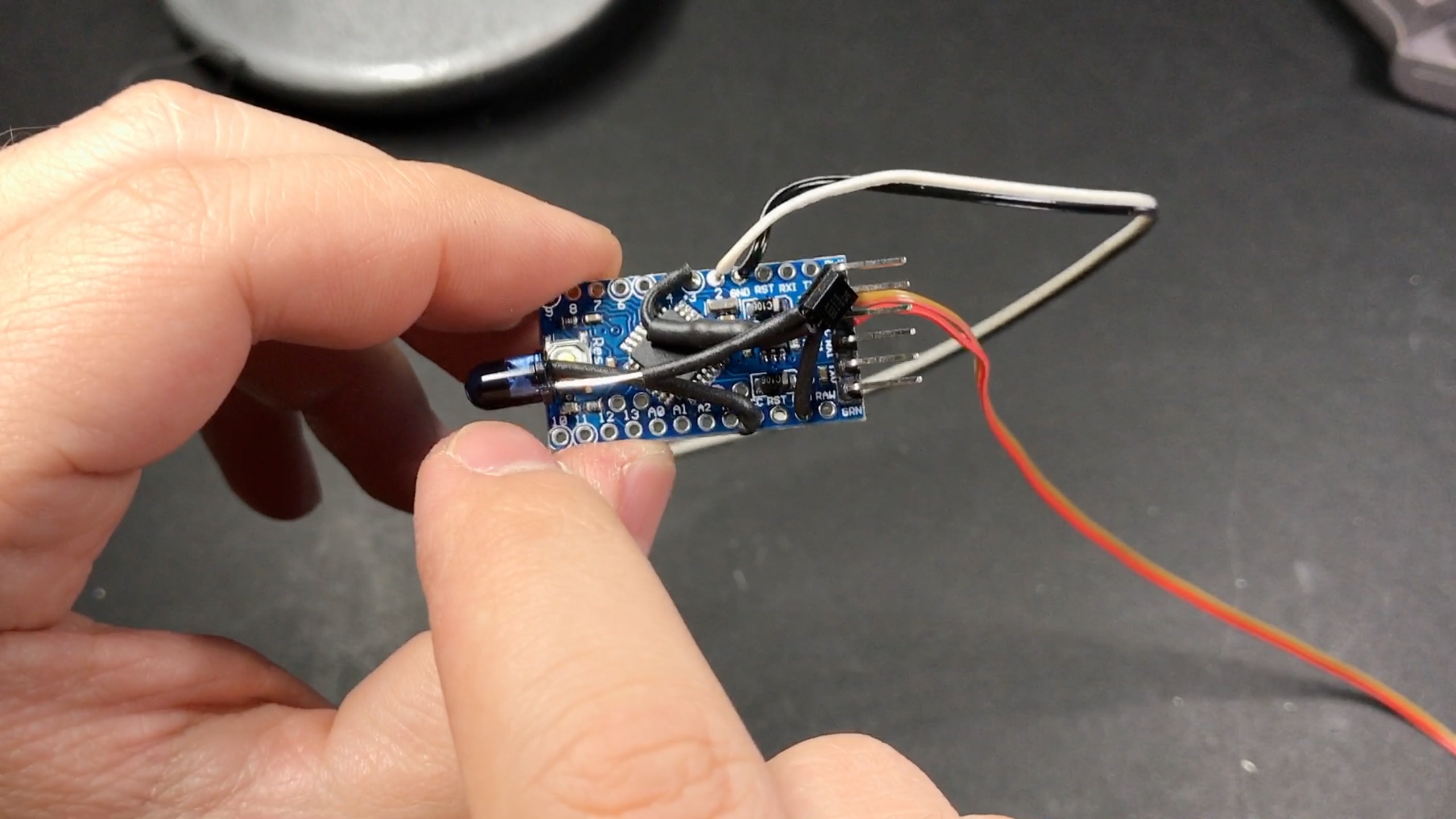
Be sure to watch the video if that was a little confusing! I also went ahead and connected two wires to pin 2 and a ground pin, which will go to the trigger in the Zapper.
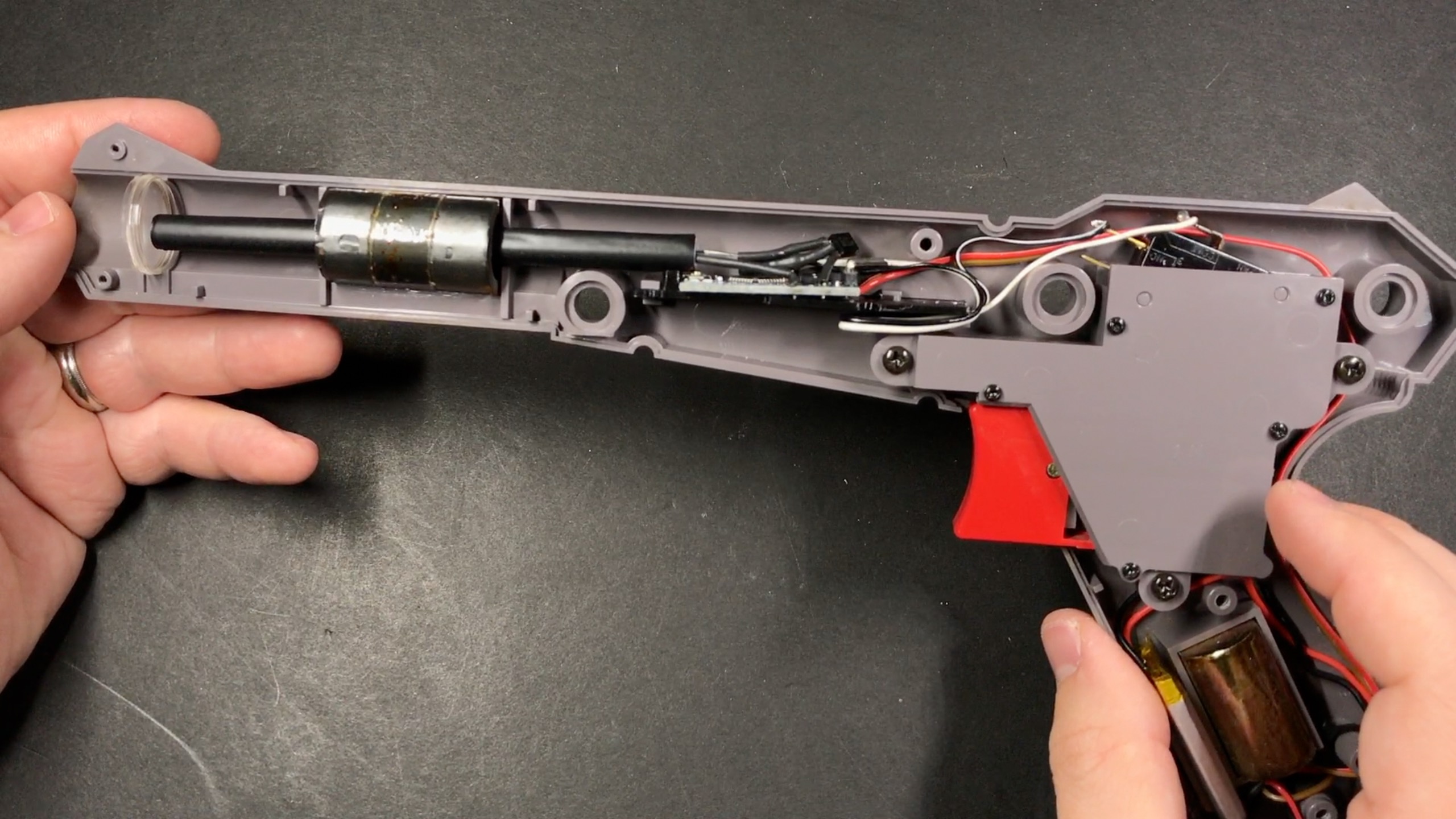
Now you’ll need to remove the sensor in the Zapper, and mount the Arduino board in its place with the LED aimed out the front. The original sensor board has a few notches cut in it at specific points to allow it to slide into place in the zapper. You can fashion something that will work out of some scrap plastic, perf board, etc. or use the 3D-printed board I designed. It fits perfectly in place of the original sensor board and has a guide for the LED ti sit on top of so you can easily position it properly:

You can download the STL file so you can print your own if you have access to a 3D printer, and you can also purchase one on the sudomod market.
Also remove the cord from the zapper.
Disconnect the two wires coming from the trigger, and connect the ones you connected to pins 2 and ground on the Arduino. It doesn’t matter which goes to which. Attach the Arduino to the 3d-printed board (or one you made yourself if you prefer) using a dab of hot glue.

Now we’ll hook up the Micro Lipo charging board. It’s pretty simple: across the top you’ll see on the left there is a 5V pin for input (which we won’t be using), followed by two ground pins, and a battery pin on the right:

Connect the ground wire that you connected to the underside of the Arduino board to one of the GND (ground) pins. Connect a few-inches-long piece of wire to the BAT pin, and connect the other side of that to one of the outer pins on the power switch. Now connect the VCC wire that you attached to the bottom of the Arduino to the middle pin of the power switch:

Again, if that’s a little confusing watch the video. 🙂
To mount it, you’ll need to cut off one of the posts that the zapper’s cord was wrapped around (as well as the corresponding peg on the other side of the shell) to make room for the charging board:

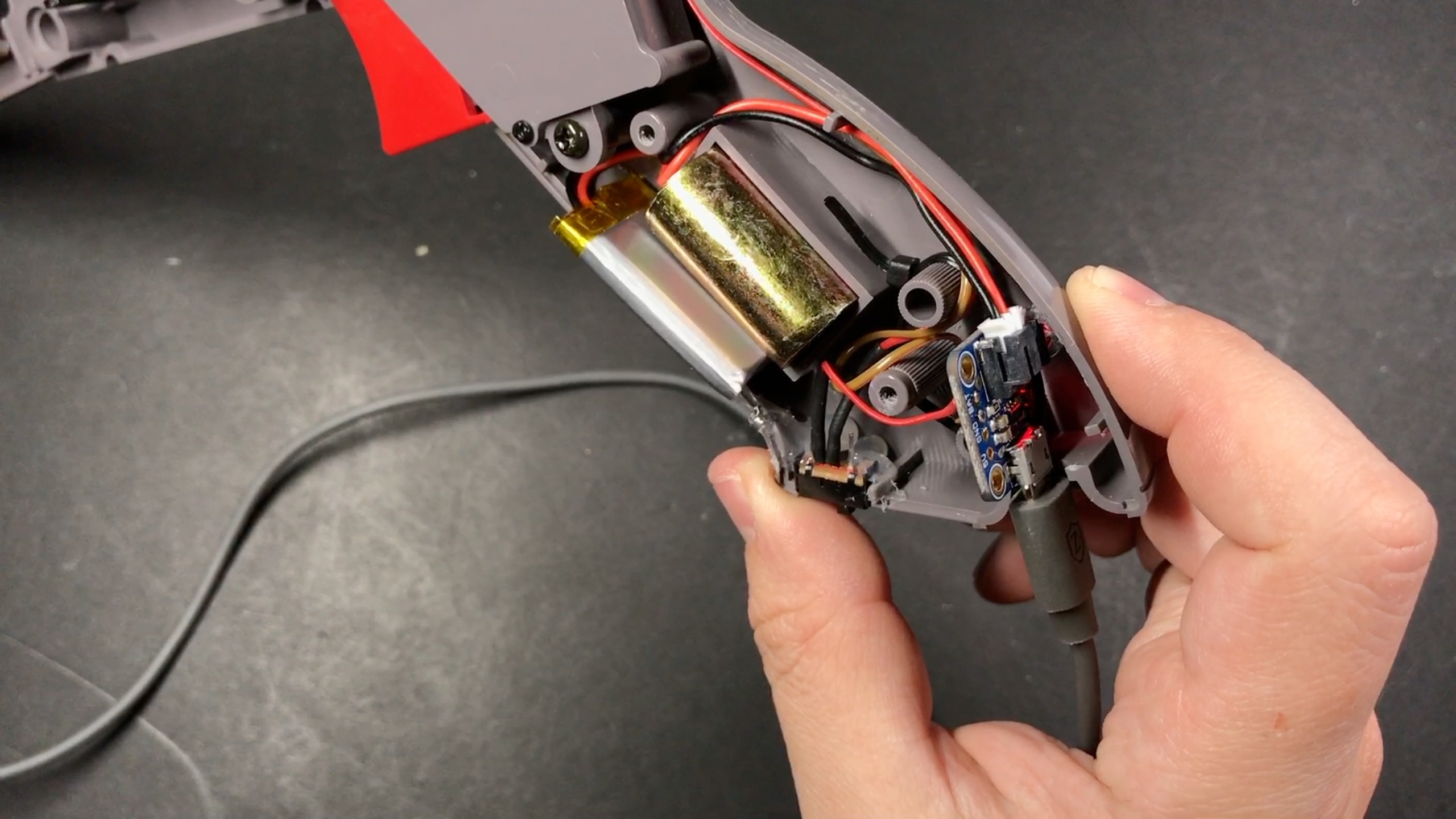
I used a zip-tie to fasten the Micro Lipo to the gun, with the micro-USB port aligned with the hole that the cord was coming out of in the bottom of the grip. It works well enough for me, but if you can’t get it to sit in there securely you may want to reinforce the board with a bit of epoxy. Cut a notch in the bottom of the grip for the switch, and glue it in place.

Before we connect the battery, go ahead and plug in a USB cable and make sure the board powers on and you see the LED on your Arduino blink when you pull the trigger. Then plug the battery into the charging board and make sure everything looks good there as far as running off the battery and charging. The battery can go right in front of the weight in the grip. I held it in place with a piece of double-sided tape.
Now, one last thing for the Zapper: Initially when I put mine together, I found that it would work pretty much regardless of where the gun was pointed. I found that light was leaking out of the sides of the zapper (this may be more of a problem for the orange zappers than the gray ones, since they are a little more translucent). To solve this, I wrapped a drinking straw in some electrical tape and placed it over the LED to block light from going anywhere but out the front of the barrel. Silly as it sounds, it works great! After doing that, the gun has to be pointed more or less directly at the sensor in order for it to work.
That’s it for the zapper! Put it back together.
The Receiver
Program the lamp sketch to your second Arduino board.
Now we’ll connect the IR receiver. When holding it as shown below, the left leg goes to pin 11 on the arduino, the middle pin is ground, and the right pin will go to one of the VCC pins on the Arduino. If you have a different receiver than the one I got, your pins may be different.

Since we’ll be chopping up the USB cable and only using a small piece of it to power the Arduino, you can use the rest of it to extend the IR receiver away from the actual box. Heat-shrink tubing is super handy here.


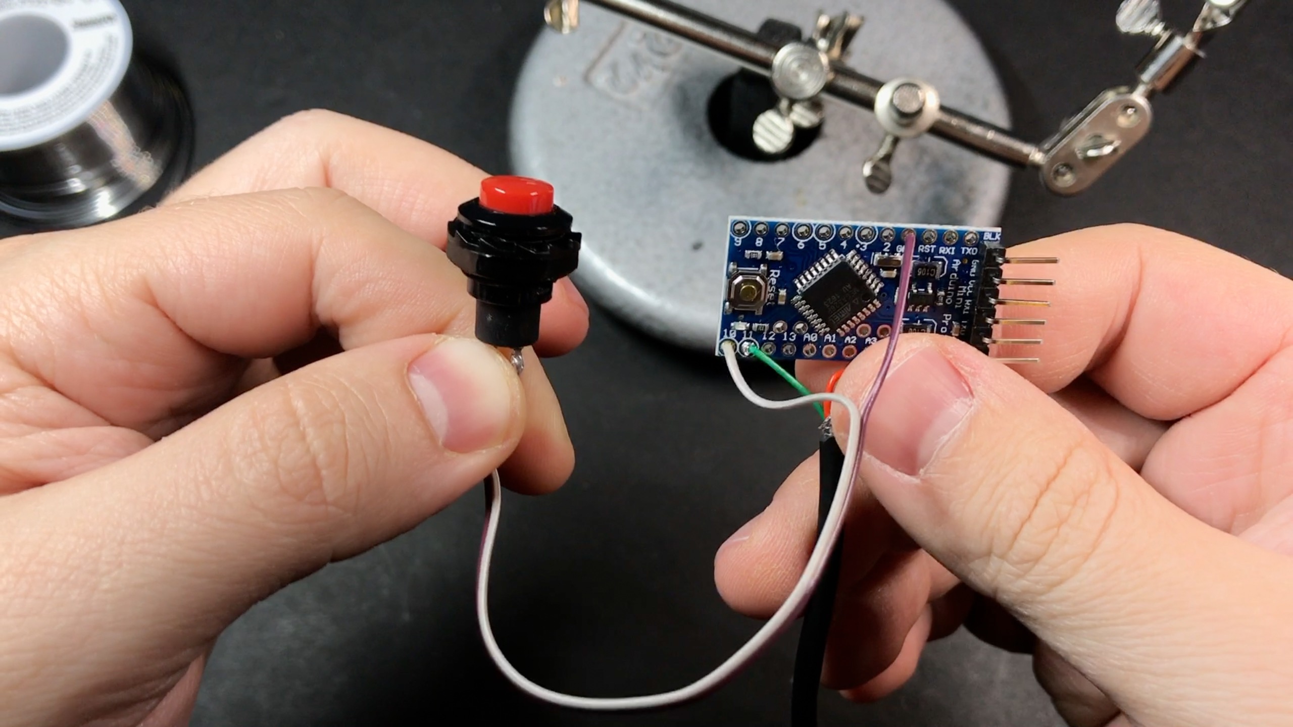
Now wire up the button that will go on the side of the project box. It goes to pin 10 and another ground pin.
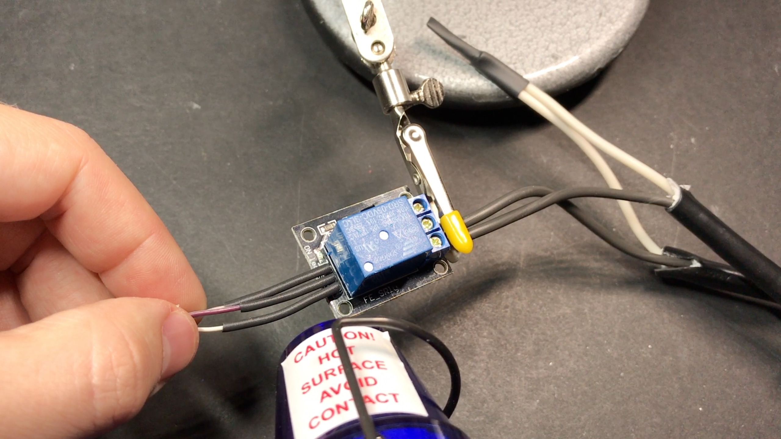
Now we’ll connect the relay. The one I used is good for 10A at 125VAC. I’m only using it for a lamp, so there is plenty of headroom if I were to connect something that used a little more power. Someone suggested using this to turn on/off a Raspberry Pi 3 connected to their TV, which is a pretty awesome idea. 😀
Just to be clear: we’re making something that plugs directly into a power outlet on your wall, which is inherently dangerous. If you aren’t comfortable or experienced with this sort of thing, you should find someone to help you who is. I’m showing how I did this, which has worked great for me so far, but proceed at your own risk!

Above you can see the relay I’m using. On the right side are the 3 pins that will be connected to the Arduino: the signal pin on bottom, which will go to pin 12 on the Arduino, the + pin above it will go to a VCC pin on the Arduino, and the – pin above it will go to ground. On the left side you’ll see 3 slots for wires – this is the actual part of the relay that switches on/off. The middle slot is common, and the other two are normally open and normally closed. We’ll be using the middle one and the top one. Cut the extension cable for the lamp down into two pieces that are around 6″ long each:

When you look at a US outlet head-on you’ll see the left slot is a little thicker than the right one — this is called the neutral side. We’ll connect both the neutral wires and secure it with some heat-shrink tubing. The right side is called the “hot” side – these are the two wires we’ll insert in to the slots on the relay, which will open/close the circuit (thus turning on/off the lamp). It helps if you twist the ends of the wires and add a bit of solder to them to prevent fraying and make them easier to insert into the relay. Tighten the screws and give it a good tug to make sure they are in there securely.

Below you’ll see I connected two sets of wires to the VCC/Ground pins shared by the header pins on the board (again, so we can still plug in/program it with the FTDI cable). One set is the power wires on the USB cable we cut up:

The he other is a 6″ or so set of 3 wires that will go to the S, +, and – pins on the relay (again, pin 12 for the signal (S) pin).
Now we just need to put everything in the project box! I used a Dremel to cut a few holes in the side of mine for the black extension cord for the lamp to plug into, the other extension cord providing power to everything, and the extension wire for the IR receiver. I also put a hole on top for the manual trigger button.

Here is how I arranged things inside the project box:

I used 2-part epoxy to attach the relay and Arduino board to the sides of the box, and a bead of it on either side of the end of the outlet that the lamp plugs into to reinforce it. I do not recommend using hot glue for this – you’ll want something stronger and longer-lasting like epoxy.
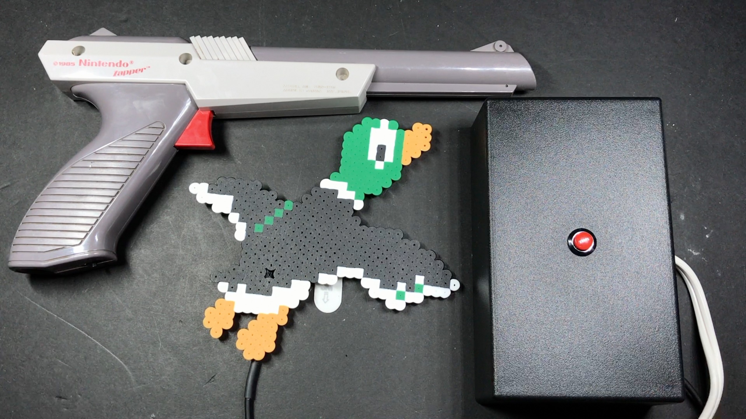
Now this last part is optional, but highly recommended. 🙂 I made a Duck Hunt duck from Perler beads, leaving a bead out in the middle for embedding the IR receiver:

I used a Command Strip (along with the plastic backing from one of the hooks) to make it easy to stick to a wall. Works great!

For the actual Perler design I used a sprite sheet from The Spriters Resource, and just picked one I liked. For tips on how to do Perler, there are a ton of great channels on Youtube – Pixel Art Shop is one of them.
And that’s it! If you have any questions, need help or just want to show off one that you made, be sure to stop by the forums!
See you next time!