- 15015298258432143883569.jpg (2.48 MiB) Viewed 8758 times
snoek09 wrote: ↑Mon Jul 31, 2017 12:56 pmA full white screen means the backlight is on. Is the ribbon cable all the way in?
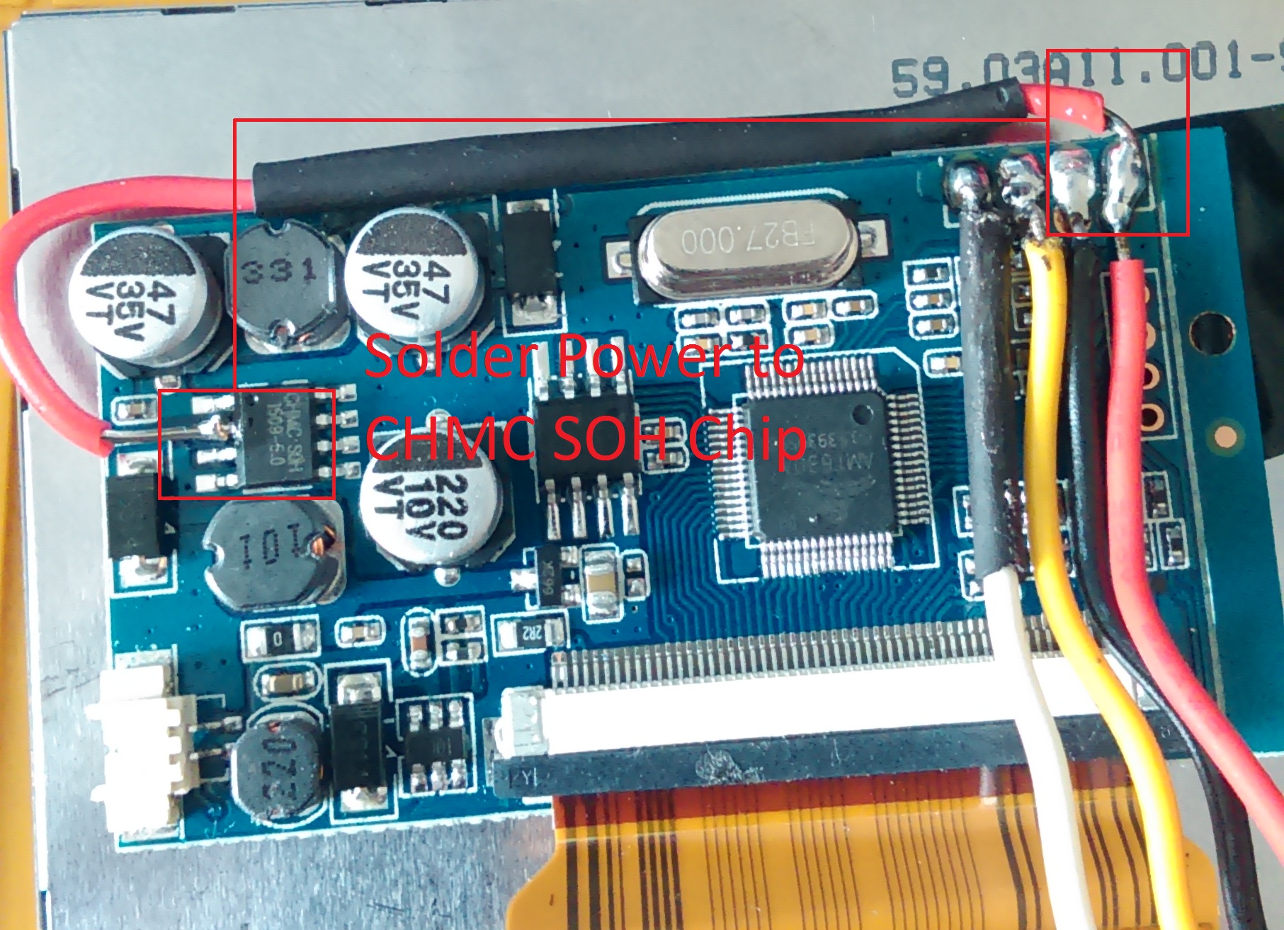
Red wire has to be on the left most pin. On the picture it's connected to the second pin which is ground.
The wire connected to the chip should also be on the left most pin.
Also, even though it's a bit too late for that now; did you check if the screen worked without modification?
And also if it didn't, did you try the second method?
If the board is broken I have one for you as I broke my screen yesterday.SpoilerShow
- 20170731_214153.jpg (1.64 MiB) Viewed 8758 times